
Datasheet


MF10-N
www.ti.com
SNOS547C –JUNE 1999–REVISED APRIL 2013
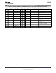
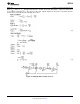
Table 1. Summary of Modes. Realizable filter types (e.g. low-pass) denoted by asterisks.
Unless otherwise noted, gains of various filter outputs are inverting and adjustable by resistor ratios.
Number of
Mode BP LP HP N AP Adjustable f
CLK
/f
O
Notes
Resistors
1 * * * 3 No
1a H
OBP1
= −Q May need input buffer. Poor
H
OLP
+ 1 2 No
H
OBP2
= +1 dynamics for high Q.
Yes (above f
CLK
/50 or
2 * * * 3
f
CLK
/100)
Universal State-Variable Filter. Best
3 * * * 4 Yes
general-purpose mode.
As above, but also includes resistor-
3a * * * * 7 Yes
tuneable notch.
4 Gives Allpass response with H
OAP
=
* * * 3 No
−1 and H
OLP
= −2.
Gives flatter allpass response than
5 * * * 4
above if R
1
= R
2
= 0.02R
4
.
6a * * 3 Single pole.
6b HOLP1 = +1
2 Single pole.
HOLP2 = -R3/R2
Copyright © 1999–2013, Texas Instruments Incorporated Submit Documentation Feedback 21
Product Folder Links: MF10-N