
Datasheet

MF10-N
www.ti.com
SNOS547C –JUNE 1999–REVISED APRIL 2013
Modes of Operation
The MF10-N is a switched capacitor (sampled data) filter. To fully describe its transfer functions, a time domain
approach is appropriate. Since this is cumbersome, and since the MF10-N closely approximates continuous
filters, the following discussion is based on the well known frequency domain. Each MF10-N can produce a full
2nd order function. See Table 1 for a summary of the characteristics of the various modes.
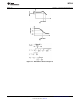
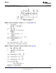
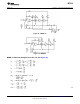
MODE 1: Notch 1, Bandpass, Lowpass Outputs:
f
notch
= f
O
(See Figure 23) (2)
f
O
= center frequency of the complex pole pair
(3)
f
notch
= center frequency of the imaginary zero pair = f
O
.
(4)
(5)
= quality factor of the complex pole pair
BW = the −3 dB bandwidth of the bandpass output.
Circuit dynamics:
(6)
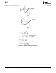
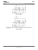
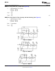
MODE 1a: Non-Inverting BP, LP (See Figure 24)
(7)
Figure 23. MODE 1
Copyright © 1999–2013, Texas Instruments Incorporated Submit Documentation Feedback 15
Product Folder Links: MF10-N