DS+60/DW30/Matrix 3000 User’s Manual 013-100149-02
DS+60 / DW30 / Matrix 3000 User’s Manual Table of Contents 1 INTRODUCTION 1.1 1.2 1.3 Projector Overview...................................................................................................... 1-1 Components................................................................................................................. 1-3 Purchase Record and Servicing ................................................................................... 1-4 2.1 2.2 2.3 2.4 2.5 2.6 Quick Setup ..............
Section 1 Introduction 1.1 Projector Overview Christie DS+60/DW30/Matrix 3000 projectors are professional quality single-chip projectors that use Digital Light Processing™ (DLP™) technology from Texas Instruments to achieve bright, crisp images. With a range of available lenses, input modules and built-in ChristieNET™ these projectors are flexible and customizable.
Section 1: Introduction ow Kn d l u r Sho jecto ou o r Y P ngs Your T hi ut A bo 1 Powering ON (a) Be patient when powering the projector ON or switching lamp operation modes. As the lamps warm up, brightness will gradually increase. (No light appears on the wall during the first 25 seconds.) On the rare occurrence a lamp does not ignite, the projector will try again several times. For more information see 3.7 - The Lamp Menu.
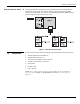
Section 1: Introduction How the projector works f The light generated by the lamp(s) is then sequentially filtered into the RGB color primaries by the spinning color wheel(s) and presented to the single chip DMD, located in the light engine, in sequence. The reflected light from the DMD chip then passes through the projection lens to the screen. Figure 1.1 How the Projector Works 1.2 Components Ensure you have received all the following components before using your projector.
Section 1: Introduction 1.3 Purchase Record and Servicing Whether the projector is under warranty or the warranty has expired, Christie’s highly trained and extensive factory and dealer service network is always available to quickly diagnose and correct projector malfunctions. Service manuals and updates are available to service technicians for all projectors. If you encounter any problems with the projector and require assistance, contact your dealer or Christie Digital Systems.
Section 2 Installation & Setup 2.1 Quick Setup The instructions provided here are for those that are familiar with the projector and wish to quickly set it up and use it temporarily. Refer to the remaining subsections of this manual for a more complete setup. Step 1 f Install a Projection Lens The projection lens is shipped separately from the projector and must be installed prior to setting up the projector. Install the projection lens as described in 4.5 Replacing the Projection Lens.
Section 2: Installation and Setup Step 4 f Connect the Line Cord The North American-rated line cord is provided with each projector. Ensure that you are using a line cord, socket and power plug that meets the appropriate local rating standards. Connect the appropriately rated line cord (supplied with the projector) to the AC receptacle located on the lower right side of the projector and the other end to an AC outlet (100-240V).
Section 2: Installation and Setup 2.2 Installation Considerations Proper installation of your projector will ensure the quality of your display. Whether you are installing a projector temporarily or permanently you should take the following into account to ensure your projector performs optimally. Installation type f Choose the installation type that best suits your needs: front or rear screen, floor mount or inverted mount.
Section 2: Installation and Setup Rear screen installations There are two basic types of rear screens: diffused and optical. A diffused screen has a surface, which spreads the light striking it. Purely diffused screens have a gain of less than one. The main advantage of the diffused screen is its wide viewing angle, similar to that of a flat screen for front screen projection. This type of screen is suitable when a wide viewing angle is required but there is low ambient room lighting.
Section 2: Installation and Setup Ambient Lighting f The high brightness of this projector is well suited for locations where ambient lighting might be considered less than ideal for projection. A typical room with ceiling lights and windows rarely requires special attention. Contrast ratio in your images will be noticeably reduced only if light directly strikes the screen, such as when a shaft of light from a window or floodlight falls on the image. Images may then appear washed out and less vibrant.
Section 2: Installation and Setup Figure 2.1. Estimating Throw Distance Vertical and horizontal position The correct vertical and horizontal position of the projector in relation to the screen depends on the lens type and the screen size. Ideally, the projector should be positioned perpendicular to the screen. This way, the image will appear rectangular instead of keystoned (trapezoidal).
Section 2: Installation and Setup Table 2. 2 Lens Offsets for DW30 (720P) Lens Type 0.8:1 fixed 1.2:1 fixed 1.3-1.7:1 1.7-2.5:1 2.5-4.0:1 4.0-7.
Section 2: Installation and Setup Figure 2.3. Lens Vertical Offsets The horizontal position of the image can be offset – that is moved to the left or right of lens center, by adjusting the fully motorized lens mount through software. The amount of horizontal offset available depends on the lens installed and if the image has already been vertically offset. Horizontal offset can also be expressed as the percentage of half the image width – the number of pixels of shift to one side of lens center.
Section 2: Installation and Setup Figure 2.4. Examples of Horizontal Offset 013-100149-02 Rev.
Section 2: Installation and Setup Figure 2.5. Lens Horizontal Offsets Lifting and transporting the projector – The projector is light enough to lift and transport a short distance. Use the indentations on the bottom of the projector as a guide for hand placement, which makes carrying the projector easier. When transporting the projector a long distance, use a stable cart or ask someone for help. Mounting There are several methods for mounting the projector.
Section 2: Installation and Setup Figure 2.6. Adjusting projector height You can modify the height of the projector to remedy a slightly uneven mounting surface by adjusting the three feet threaded into the bottom chassis. Turn each foot clockwise or counterclockwise until the project is level on all sides. (Figure 2.7) Figure 2.7. Adjust Projector Height NOTE: The front of the projector can be raised up to 10 degrees. (Figure 2.8) Figure 2.8.
Section 2: Installation and Setup 2.3 Connecting Sources Sources connect to the Input Panel located at the back of the projector. See Figure 2.10. The upper right corner (INPUT 1) typically accepts an RGB signal from an external analog RGB source, or it can also be used for YPbPr signals or additional video sources. The DVI-I connector at INPUT 2 accepts digital or analog display signals from a computer.
Section 2: Installation and Setup Figure 2.11. Connecting RGB and Sync NOTES: 1) If for some reason the projector fails to recognize a signal as an RGB signal, specify the Color Space option within the Image Settings menu. See 3.7, Adjusting the Image. 2) To connect YPbPr signals–such as from DVDs or analog HDTV sources–to INPUT 1, use the red, green and blue BNCs as described in YPbPr Signals (below). 3) Use the computer cable provided, to connect some devices to the DVI-I connector at Input 2.
Section 2: Installation and Setup Composite and S-Video f INPUT 3 and INPUT 4 provide simultaneous connection of both a composite video source (INPUT 3) and an S-Video source (INPUT 4). See Figure 2.13. Figure 2.13.Connecting Composite or S-Video sources DVI Digital Video f Use the DVI-I connector at INPUT 2 to connect either analog or digital video devices to the projector.
Section 2: Installation and Setup 2.4 Connecting Communications As an alternative to the projector’s keypad or remote, you may wish to communicate with the projector using a PC or other controller. Such a device sends commands and receives feedback via serial links (RS232 and RS422), Ethernet or GPIO communications to the projector, all described below. IR Remote f As desired, direct the projector’s IR remote towards the display screen or the projector’s IR sensors.
Section 2: Installation and Setup Figure 2.15. Connecting RS422 Ethernet Communications To add the projector to an existing Ethernet network with other equipment such as controllers and other projectors, connect standard CAT5 Ethernet cable between your Ethernet controller (or hub) and the Ethernet port on the side of the projector. CONNECTING TO A PC: If you are connecting the Ethernet port directly to a PC (rather than a network or hub), make sure to use a crossover Ethernet cable.
Section 2: Installation and Setup Regardless of how it is assigned, once a projector has a valid and unique address it will respond to commands sent to this address. To determine the projector’s current IP address, consult the Status or Communications menus. Refer to Section 3 for further information about setting up and using a projector connected via Ethernet.
Section 2: Installation and Setup Note that communication parameters such as baud rate must be set to match the particular controlling device before connecting as a network—refer to the documentation that came with your controlling device in order to determine the proper baud rate. See 3.6 - Adjusting System Parameters and Advanced Controls if you need help changing the projector baud rate. In addition, set the Network Routing to “RS232 and RS422 Joined” if you want to reach all projectors.
Section 2: Installation and Setup NOTES: Only the port and IP address of the projector can be changed. The subnet mask is fixed (255.255.255.0). CHANGING THE PORT#: On some Ethernet networks, firewall restrictions may require that the port number of the projector be changed from its default of 3002. If so, enter a new port number in the Ethernet Settings menu or include the new port# in an XIP serial command sent to the projector.
Section 2: Installation and Setup 2.6 Power Connection Plug the line cord to the AC receptacle located on the right hand side of the projector and the three-pronged end into a grounded AC outlet (Figure 2.22). The input voltage to the projector must be capable of 100 – 240 VAC. See also Section 6 – Specifications for complete details on all power requirements. The North American-rated line cord is provided with each projector.
Section 3 Operation This section explains how to effectively operate the projector once it has been installed. It is recommended that you read this section and familiarize yourself with the components and the available menu options before you begin using your projector for the first time. 3.
Section 3: Operation AC receptacle f (3) The AC receptacle is located on the right side of the projector (opposite side of lamp doors). Use this outlet to plug in an appropriately rated line cord. See 2.6 Power Connection for details. The input voltage to the projector must be capable of 100 – 240 VAC. See also Section 6 – Specifications for complete details on all power requirements. Adjustable Feet f (4) Located on the bottom of the projector are 3 adjustable feet.
Section 3: Operation Front & Rear IR Sensors f (6) & (11) The two IR sensors located on the projector receive transmissions from the IR remote from up to 100 feet away. It is important to keep the transmission path to these sensors unobstructed for uninterrupted communications with the projector. The front IR sensor is located next to the projector’s nameplate and the rear IR sensor is located just below the input panel.
Section 3: Operation IR Remote f The IR remote controls the projector by way of wireless communications from a battery-powered infrared (IR) transmitter. Use the IR remote the same way you would use a remote control supplied with a TV or VCR. When making key presses, direct the keypad either toward the screen or toward the front or rear of the projector. One of the two IR sensors on the projector will detect the signals and relay the commands for internal processing.
Section 3: Operation Wired IR Remote f You can convert the IR remote into a wired IR remote using the cable provided with the projector. Connect one end into the remote and the other to the mini stereo connector on the input panel labeled REMOTE. The wired remote is recommended when: • the built-in keypad is inaccessible • the lighting conditions are unsuitable for proper IR transmission NOTE: Leave the batteries in the wired remote for the laser key ( ) to work.
Section 3: Operation Table 3.1. Auto Setup What an “Auto Setup” Does OPTIMIZES: SETS TO DEFAULT: Pixel Tracking Contrast Pixel Phase Brightness Size and Blanking Auto Input Level (off) Vertical Stretch Detail (if video source) Position Filter Input Levels Luma Delay NOTE: You must have an unlocked channel present to use Auto Setup. Channel Channel Press to select a specific source setup (channel) defined and stored in projector memory.
Section 3: Operation Contrast Contrast to change the amount of white in your images. Use keys until Press you reach the desired level of contrast—for best results, start low and increase so that whites remain bright but are not distorted or tinted, and that light areas do not become white (i.e., “crushed”). Conversely, low contrast causes dim images. See 3.5, Adjusting the Image (Image Settings subsection). Contrast Bright Brightness Press Bright to increase or decrease the amount of black in the image.
Section 3: Operation Shutter Shutter Press and hold Shutter for two seconds to toggle the internal mechanical shutter blade closed or open with a single keystroke, or press and release Shutter followed immediately by (open) to guarantee the correct toggle (useful if (closed) or you are unsure of the present state). Alternatively, press Shutter Shutter to toggle from the present on/off state. A closed shutter blanks the display (turns it to black).
Section 3: Operation NOTES: 1) The "Broadcast Keys" option in the Communications menu must be selected for only one (any) projector in a serial network. The keypad in use must be OFF (disabled) for the remaining projectors. See also 3.6, Adjusting System Parameters and Advanced Controls. Enter to select a highlighted item, to toggle a checkbox, or to accept a parameter Press adjustment and return to the previous menu or image.
Section 3: Operation Laser Press to activate the laser pointer on the remote. This feature is useful when making presentations - just point the remote at the screen to highlight an area of your key depressed while presentation. Keep the you are pointing. Release it to turn it off. The CAUTION laser pointer works best in an environment where ambient lighting can be controlled. LASER RADIATION DO NOT STARE INTO BEAM NOTE: The batteries must be in the wired IR remote for the key to work. 3.
Section 3: Operation Figure 3.5. Context-sensitive Help From presentation level, press Help to access general Help Topics. Scroll as necessary within a topic. Press Help or Exit to return to your presentation. Figure 3.6. Accessing General Help Topics Time-outs f If a slidebar, menu or message is displayed you have limited time in which to make a keypad entry before the projector returns to presentation level and the graphic disappears. These time-outs may vary depending on what is displayed.
Section 3: Operation Once selected, change the setting as desired (see below) and press return to the current function menu. to save and Slidebars in menus – The current value for a given parameter, such as size or vertical stretch, appears to the left of its slidebar icon (adjustment window). This number often expresses a percentage, or it may have units associated with it (such as pixels, degrees Kelvin, etc.), depending on the specific option.
Section 3: Operation If you prefer to quickly scroll through a list without first pulling it down, highlight the option and use . Press when the desired choice appears. to jump between pages in an extra long pull-down list. NOTES: 1) Press or Exit while in a pull-down list to cancel any change. 2) Press Editing Text f ACTIVATE THE EDIT WINDOW: To enter or edit text, highlight the desired parameter (such as a channel name) and press to activate its adjacent edit window.
Section 3: Operation NOTES: 1) Once you enter the first digit, this digit replaces all old digits. 2) If you press any non-numbered key, the number entered up to that point is accepted and updated as the new value. 3) Press Exit to cancel editing of numerical values. 3.4 Using Inputs and Channels NOTE: See Section 2, Installation and Setup, for details on connecting sources to the projector.
Section 3: Operation Shown at right is a sample channel list as would . This is typically called be available from the channel list. Channel key may display a channel list NOTE: The or not, depending on what you have defined for “Display Channel List” (see Menu Preferences later in this section). Channel In order to access channels by using on the keypad, you must first create the channels. See below.
Section 3: Operation What Channels f All available channels are listed in the Channel Setup menu, which describes how Are Defined So Far? each channel can be accessed and which serves as the gateway for editing, copying and deleting channels. From the presentation level press Menu to display the Main menu. To display the Channel Setup menu, press 3 , or move the highlight to the Channel Setup option and press . The Channel Setup menu will appear (see sample at right), with the active channel highlighted.
Section 3: Operation FUNCTIONS WITHIN THE CHANNEL SETUP MENU —To copy, delete or edit a channel, highlight the desired channel in the Channel Setup menu and do one of two things: • Press Func if you want to copy the selected channel or delete this or other channels. See Copying or Deleting a Channel below. • if you want to edit channel setups (i.e., non-image related parameters) Press for the selected channel. See Editing a Channel Setup, below.
Section 3: Operation TO DELETE MULTIPLE CHANNELS, highlight any channel in the Channel Setup menu and press Func to go to the Channel Copy/Delete submenu. Select “Delete Unlocked to delete all unlocked channels. Or select “Delete All Channels” Only” and press to delete all channels, even those that are locked. In either case, the current channel will remain but will be redefined from projector defaults. NOTE: For any deletion, a confirmation box appears to make sure that you really want to delete.
Section 3: Operation • AUTO SOURCE: If checked, (default), the projector can automatically locate this channel when an incoming input signal matches. If not checked, the projector can on the locate the selected channel only when it is directly selected via keypad—and a change in input signal will not result in a channel change. Channel 3.5 Adjusting the Image • checked, all of the image settings for this channel are disabled.
Section 3: Operation Size and Position Menu f In the Size and Position menu, you can increase or decrease the size of your image, change its proportion (aspect ratio), move the image to a specific area of the screen, and refine other related parameters. Use Size and Position controls to match the image precisely to the screen used at the site. Refer to "Using Slidebars and Other Controls" (earlier in this section) if you need help using any of the options and controls.
Section 3: Operation • Select “NO RESIZING” to display the image in its native resolution, which may or may not match the projector’s resolution. For example, for a source with a native resolution of 800 x 600, “No Resizing” in an SXGA+ projector will use the central 800 x 600 pixels and have a black border—the black border areas are unused areas. See below. • Select “FULL SIZE” to use all pixels for displaying the image, regardless of source or original aspect ratio.
Section 3: Operation • Select “ANAMORPHIC” to display an anamorphic image in its native 16:9 aspect ratio. The image will fill the screen from side-to-side and be centered between black bars at top and bottom. Size “Size” controls both the image width and height in tandem, maintaining the current aspect ratio (proportion) of the displayed signal data. Vertical Stretch “Vertical Stretch” adjusts the height of the image while keeping the width constant.
Section 3: Operation H-Position This option moves the image right or left within the area of available pixels. NOTE: The value shown represents where the approximate center of the image lies in relation to the total number of pixels available horizontally. This varies widely according to the signal—watch the image while adjusting. V-Position This option moves the image up or down within the area of available pixels.
Section 3: Operation PLUG & DISPLAY (EDID): By default, a Plug & Play (EDID) source outputs a signal according to the EDID information provided by the projector. To override this information and display in a different format (for example, if your Plug & Play [EDID] device does not support the projector’s resolution and/or frequency), select the desired Plug & Play (EDID) resolution from the list. Any daisy-chained projectors will also display according to the chosen Plug & Play (EDID) format.
Section 3: Operation Brightness (SHORT CUT: Press Bright and adjust the slidebar.) “Brightness” increases or decreases the amount of black in the image (0-100). For best results, keep close to 50. Start with a high value and decrease so that dark areas do not become black (i.e., are “crushed”). Conversely, high brightness changes black to dark gray, causing washed-out images. Gamma (SHORT CUT: Press Gamma and adjust the slidebar.
Section 3: Operation Noise Reduction “Noise Reduction” is similar to the “Filter” control, but operates in the post-sampling digital domain with a more subtle effect. Higher settings are most useful for clearing up noisy RGB images such as those from a PC. Adjust as desired, keeping in mind that reducing noise (which reduces high frequencies) may also soften the image. Color Space “Color Space” determines how the color components of an analog input signal are decoded for accurate color in the display.
Section 3: Operation VIDEO STANDARD: For all but the more unusual video standards available in the world, the projector automatically detects the incoming horizontal and vertical frequencies and sets the projector’s processing of this signal to the corresponding standard. The current video standard name appears in the Video Options submenu, and includes an “A” if it has been auto-detected.
Section 3: Operation DECODER LUMA DELAY – This control affects any incoming composite or S-video signal, delaying the luma signal (intensity) in relation to the chroma (color). In the image, increasing the luma delay will move luma (seen as a shadow where colors overlap) to the right slightly, with colors remaining in place. Decreasing this delay will move the shadow slightly to the left. If necessary for your current source, adjust so that no shadows occur with adjacent colors.
Section 3: Operation then delete the checkmark and exit. The Auto Input Level is automatically turned off upon exiting the Input Levels menu. BLACKLEVELS AND DRIVES – To check your image levels and adjust these controls: 1. Make sure overall “Contrast” and “Brightness” settings are both set to near 50. NOTE: Not required for “Auto” adjustment. • 2. 3. 4. 5. 6. Contrast = 50 (approx.) Bright • = 50 (approx.
Section 3: Operation black and white are known to be at opposite edges of the image, you can watch these isolated areas while adjusting individual blacklevels and input drives until both black and white edges are just visible and distinguished from neighboring pixels. Images from this source will then display correct blacks and whites without crushing. See Figure 3.14. Adjusting Input Levels Using the Peak Detector: 1.
Section 3: Operation Advanced Image Settings — SUBMENU Use the Advanced Image Settings submenu to make the adjustments necessary for lesser-used but more specialized applications on your projector. This control applies a default video, graphics or simple gamma table or “curve” to your images, controlling the intensity of mid-level colors and producing maximum contrast, brightness and color performance.
Section 3: Operation Adjustment” options or color temperatures suit your application, select one of four color gamuts previously defined by a user (User 1, 2, 3, 4). A “User” option applies a customized color performance in which the user has precisely set the hue and intensity of each color component in the Color Adjustment by X/Y or Color Saturation submenus. It is most often needed with multiple-projector applications.
Section 3: Operation Simulation 3D — SUBMENU OF ADVANCED IMAGE SETTINGS This submenu allows you to adjust the timing between the input signal and its appearance on screen. This is most useful in applications where you want to match the timing of the projector to other equipment, such as a video recording device in broadcasting environments. FRAME DELAY MONITOR — This Figure 3.15. value changes as it monitors the latency between input and output.
Section 3: Operation DETAIL THRESHOLD — Use “Detail Threshold” to define at what frequency level the “Detail” control will begin to magnify high frequencies, which adds details back into the image. Raise the threshold to ignore more of these high frequencies, and lower the threshold to magnify more of these frequencies. A setting of “0”, for example, means no noise will be ignored and all will be magnified.
Section 3: Operation Menu Preferences — SUBMENU Adjust the appearance, content and/or location of on-screen menus and messages. Enter a checkmark to enlarge menus and their text. You may have to adjust “Menu Location” to accommodate the increased menu area. LARGE MENU FONT — MENU LOCATION — Use the pull-down list to choose a pre-defined default or customized location for the display of all on-screen menus. To create a custom menu location quickly, choose a preset that is closest to the desired location.
Section 3: Operation • Startup And No Signal – A splash screen appears at startup only if there is no source signal. To replace the default “Christie logo” splash screen (or other) with one of your own, use KoRE Librarian to download the desired .bmp to the projector. This will overwrite the current splash screen content in projector memory.
Section 3: Operation Figure 3.17. Using the “Network Routing” Option RS232 AND RS422 JOINED: Messages originating from an RS232 or RS422 controller will be relayed to all RS232or RS422 ports. Any Ethernet communication, however, will not. RS232 AND ETHERNET JOINED: Messages to and from the RS232 ports will also be relayed to the Ethernet port, and vice versa. Any RS422 communications will be isolated. ALL JOINED: All messages reach all ports, regardless of type.
Section 3: Operation by a DHCP server or other user. It takes approximately 10 seconds for the projector to respond at its new address. PORT: On some Ethernet networks, firewall restrictions may require that the port number of the projector be changed from its default of 3002. If so, enter a new valid port number here. SUBNET MASK AND DEFAULT GATEWAY: The Subnet Mask and Default Gateway are automatically assigned when DHCP is enabled.
Section 3: Operation DMX Channel Function Base Shutter Base + 1 Slider Lock Base + 2 Base + 3 Input * Channel * Base + 4 Lens – Vertical * † Base + 5 Lens – Horizontal * † Base + 6 Lens – Focus * † Base + 7 Lens – Zoom * † Base + 8 Power * Base + 9 None Value 0 – 64 65 – 192 193 – 255 0 – 254 255 1–8 1-99 0 1 – 254 255 0 1 – 254 255 0 1 – 254 255 0 1 – 254 255 0 1 – 254 255 Open No Action Closed Locked Unlocked * Input # Channel # Lens Down Stop Lens Up Lens Right Stop Lens Left Negativ
Section 3: Operation To disable both IR sensors, you cannot use the IR remote keypad to select the second OFF setting. This safeguard prevents accidentally disabling an IR keypad while you are using it. Instead, use either the built-in keypad or a wired remote (optional) to set the remaining active sensor to OFF. The projector will no longer respond to an IR remote keypad. NOTE: Protocols B – G are used for rental staging applications.
Section 3: Operation memory, typically creating one or more “squeezed” or stretched areas in the display. If no custom warps have been created, the User options will have no effect. 2D KEYSTONE: Move one or more corner points as desired for your application. Traditionally, keystoning adjustments simply correct an image in which opposing sides are inclined away from each other (caused by tilting the projector in relation to the screen). If the lens surface is parallel to the screen and settings are 50.
Section 3: Operation Use to correct a keystoned image shape in which both sides of the image are inclined toward the top or bottom edge. Keystone is typically caused by tilting the projector in relation to the screen so that the lens surface and screen are no longer parallel to each other. (Figure 3.18) Figure 3.18. Brightness Uniformity — SUBMENU Brightness Uniformity provides further refinement of displays already matched for their primary colors and overall light output.
Section 3: Operation From the factory, the projector can utilize any of the 3 pre-defined color performance settings identified at right (default=Max Drives), or colors can be driven on the basis of color temperature. For most applications, one of these gamuts will produce accurate and realistic colors from a variety of sources. They can be applied at any time in the Advanced Image Settings Figure 3.19. Color Gamut Choices menu (“Select Color Adjustment”), and are not adjustable.
Section 3: Operation four “User” color gamuts needed for your environment and applications. Apply at any time in the Advanced Image Settings menu. Figure 3.21. CIE 1931 Chromaticity Diagram NOTE: Keep new x,y coordinates within the original color gamut triangle shown here. PROCEDURE FOR X,Y ADJUSTMENTS: See 3.10, Using Multiple Projectors. COLOR SATURATION: Use this submenu if you do not have specific color coordinates in mind and will simply judge color performance by eye or meter.
Section 3: Operation System Configuration f Test Pattern Choose the desired internal test pattern to display, or select OFF to turn off a test pattern. Alternatively, use the Test key for cycling through test patterns. DIAGNOSTICS / CALIBRATION NOTE: There is a center line (both horizontal and vertical) in the Edge Blending test pattern. The intersection of these lines is the true center of the projector’s display area.
Section 3: Operation Two sets of values are automatically saved with these controls—one value for Input #1, and one for Input #2 (analog). The current set of values depends on which source is in use. This enables a source to be processed correctly via 2 different inputs. Figure 3.23. Using “Odd Pixel Adjustment” NOTES: 1) Adjust offset before gain, since offset affects gain. 2) A value of 128 represents no change in normal odd pixel offset or gain.
Section 3: Operation Peak Detector The “Peak Detector” is a fast method for defining individual input levels, and can improve the accuracy of input levels set by the Auto Input Level function. Enabling the “Peak Detector” activates a special operating mode for detecting only pixels that are considered black or white—all other levels are displayed as a mid-level gray.
Section 3: Operation 3.7 Working with PIP or Seamless Switching PIP (Picture-in-Picture) and Seamless Switching are independent but related projector features that both utilize two image processing paths within the projector. In the case of Picture-in-Picture, this double processing enables you to display two different images simultaneously – typically a smaller “secondary” image within a large “primary” background.
Section 3: Operation Swap Main and PIP Image Toggle the current picture-in-picture relationship so that the primary (main) image becomes secondary (PIP), and the secondary image becomes primary. Swapping is available only when PIP is enabled. NOTE: There may be a slight delay when swapping the Primary and Secondary images. PIP Enable Short cut: Press remote. on the Toggle to display from two sources at once (Picture-inPicture) or the primary source only.
Section 3: Operation PIP Border Width Set the desired line thickness for your PIP window border. PIP Border Color Select the desired color for the PIP window border. NOTES: 1) Numbers 7 and 8 on the Picture-in-Picture and Switching submenu control switching parameters. 2) Disable PIP in order to work with Seamless Switching. 3) Disable PIP and Best Switching for Interlaced sources > 35kHz.
Section 3: Operation Numbers Select Main Image Use Numbers Select Main Image to use the numeric keys #1-8 as input keys. This remapping of the keypad (see right) can be particularly useful with PIP displays, providing a convenient shortcut for changing the primary (background) image without first having to return to the Main menu. Select “Always” to use the keys in this manner all of the time, even with single displays. For normal keypad function, select “Never” (default).
Section 3: Operation • In Single Lamp mode, the projector will try to strike the lamp again in 90 seconds (considered re-strike #1). Only after the third attempt (re-strike #2) will the projector declare the lamp as “Failed to Strike” (in Lamp submenu) and automatically switch to the single lamp operation mode for the lamp that was not ignited. All lamp specific menu options will then change to reflect the true lamp operation mode of the projector.
Section 3: Operation Figure 3.24. The Lamp Menu LAMP MESSAGE - Enter a checkmark to enable a warning message that will appear upon power-up when the lamp has reached the specified lamp limit and should be replaced. Delete the checkmark to prevent display of this message—instead, when your lamp expires only the status LED display will provide the visual warning to replace the lamp. The LED’s next to the built-in keypad will flash “LP” when lamp time has expired. The lamp should be replaced.
Section 3: Operation NOTES: 1) The projector will automatically shutdown if it detects both lamps have “failed” (this includes lamps not installed). 2) The lamp operation mode will not automatically switch to a previous mode once a “failed” lamp is replaced. It must manually be selected. 3) It takes approximately 25 seconds for a cold lamp to reach full brightness when it is first turned on. 4) Power is cut to a lamp only when the lamp operation mode is switched to the other lamp.
Section 3: Operation 3.9 Status Menu The read-only Status menu lists a variety of details about the standard and optional components currently detected in the projector. Refer to the Status menu for versions of hardware and software installed, the type (size) of lamp, the hours logged in total and for a specific period (such as a rental period), and for your projector model name and serial number.
Section 3: Operation Color Adjustment Procedure Once the Color Primary Settings are calibrated for the site (see above), use the Color Adjustments by X,Y or Color Saturation menu to further refine each projector’s fundamental colors so that the hue and intensity of each color appears the same from one display to another. Once matched, you will have created a single new shared range of colors or “color gamut” that all of your projectors can produce.
Section 3: Operation Figure 3.26. Copy X/Y Values into All Projectors 6. In each projector, judge by eye and adjust x/y coordinates slightly in the following manner: To match reds, decrease “Red X” until full field red screens match. To match greens, decrease “Green Y” until full field green screens match. To match blues, increase both “Blue X” and “Blue Y” until full field blue screens match. NOTE: For speed, enable the “Auto Color Enable” checkbox.
Section 3: Operation 7. All screens should now be color-matched and the will remain matched upon exit from the menus. Apply this new “User” gamut to a source at any time by selecting it in the “Select Color Adjustment” list accessed in the Advanced Image Settings menu. Using the Color Saturation Menu for Color Matching You may prefer to use the Color Saturation menu to match colors across multiple screens.
Section 3: Operation ADJUST COLORS FIRST—Always adjust the primary colors as described in the “Matching Colors in Multiple Screens” procedure (above) before attempting to work with Brightness Uniformity. This ensures that primary colors, color temperature, and maximized light output are all well-matched from one screen to another. These matches are needed before you can achieve good Brightness Uniformity results.
Section 3: Operation 1c) Select the 13 Point test pattern for display. This pattern provides 9 screen “zones” with 13 targets. FOR BEST RESULTS: Rather than examining the CENTER of each zone when assessing Brightness Uniformity adjustments, focus on extreme EDGES as indicated in the illustration at right. 1d) In either Color Adjustments menu, select a “User” color. Then: • • If you have created a “User 1” color gamut (recommended) for a wellmatched wall, continue to Step 1e.
Section 3: Operation blue, too red or too green, go to the Left Uniformity menu and adjust the colors (i.e., change their light output) until all portions of the left side closely match the center color temperature. Adjust an edge first (focusing on its center), then adjust its corners. See Figure 3.28 Figure 3.28.
Section 3: Operation Step 4: Readjust Color Temperature (level of red/green/blue) in 8 Zones 4a) Return to Steps 2a & 2b and, if necessary, fine tune the zones so that they all still exhibit a single color temperature. Canceling Brightness Uniformity If you do not want to use or apply Brightness Uniformity settings, delete the checkmark from the “Uniformity Enable” checkbox at the top of the Brightness Uniformity menu.
Section 3: Operation Main Functions Use standard edge blending controls to set the precise width, shape and midpoint you need to blend overlapping edges together smoothly. Blend Width determines how much area is used for blending along an overlapping edge. Slidebar values represent the number of 8-pixel steps used for the blend. For example, a setting of “3” creates a blended edge 24 pixels wide. A setting of “0” signifies no blending.
Section 3: Operation Show Blending Overlap turns your defined blend width area to solid gray so that two adjacent images can be seamlessly aligned simply by overlapping their gray bars, if needed. Toggle the Show Blending Overlap off to reactivate the blend effect. Other Functions For convenience, the Edge Blending submenu also includes related options for enabling a specific color and/or test pattern, or for working with colors or the lamp.
Section 3: Operation 3. SET STARTING POINTS FOR ADJUSTMENT: Set all blend widths to 0. Go to “More” and set everything in the Edge Blending (2) menu to 50. Figure 3.35. Set Starting Points for Each Projector 4. SET BLEND WIDTH: On one projector, increase the Blend Width for an overlapping edge (for example, if the projector’s image is on left, its right edge overlaps the adjacent image—adjust Right Blend Width). Use the same setting on the second projector for this shared edge. 5.
Section 3: Operation VIA ASCII MESSAGING — Connect a serial link between your controller and the RS232 or RS422 port (recommended), or open an Ethernet socket (i.e., Telnet) between your controller and the valid projector address. Valid ASCII codes and messages are documented in the Christie Serial Communications document available at the Christie website. VIA WEB INTERFACE — Connect your PC to the projector’s Ethernet port.
Section 3: Operation User Errors f Invalid User Entry A keypad entry not recognized by the projector triggers a short on-screen error message identifying the problem. For example, if you specify a channel number that is not available, the message “Invalid Channel will appear. Or if you try to enter the wrong password, you’ll see “Invalid Password”. Press or Exit to clear the message and try again.
Section 3: Operation should be reported to the manufacturer. You can press Exit Exit to remove the message, but for best results you should reset the projector—power the projector down and up again with the (power) key. System Errors A system error message indicates that a serious malfunction has been detected and must be reported to the manufacturer as soon as possible (see Status LED Codes, below). The projector will no longer operate and must be reset—power the projector (power) key.
Section 3: Operation Error Codes f Code Description GENERAL 12 13 14 15 16 17 18 Software bug. Contact dealer/factory. Flash memory corrupted. Download new software. Engineering only programming is complete. Call Christie, replace TIPM. Attempting to download code without being in boot mode Invalid interrupt. Power off/on. If it persists, contact dealer/factory. Forced boot mode. Keys held down too long.
Section 4 Maintenance 4.1 Warnings and Safety Guidelines The projector is an international regulatory agency approved product designed for safe and reliable operation. It is important to acknowledge the following precautions while operating the projector to assure complete safety at all times. WARNING Always remove the lens when shipping the projector. WARNING NEVER look directly into the projector lens. The high brightness of this projector could cause permanent eye damage.
Section 4: Maintenance Projector Location f Operate the projector in an environment, which meets the operating range as specified in Section 6 – Specifications. • • • Do not operate the projector close to water, such as near a swimming pool. Do not operate in extremely humid environments. Do not place the projector on an unstable cart, stand or table. A projector and cart combination should be used with care.
Section 4: Maintenance • The projector is equipped with a three-wire plug having a third grounding pin. This is a safety feature – if you are unable to insert the plug into an outlet contact an electrician to have the outlet replaced. Do not defeat the safety purpose of this grounding-type plug. Ventilation f Slots and vents in the projector provide ventilation. Never block or cover these openings. This ensures reliable operation of the projector and prevents overheating.
Section 4: Maintenance 4.2 WARNING Cleaning and Maintenance Guide Always power down and unplug the projector before cleaning or servicing. Table 4.1. Maintenance Guide Part Description Frequency Lens As required Lamp Module (300 W P-VIP) As required 1500 hours or sooner if required Covers As required 4-4 Christie DS+60/DW30/Matrix 3000 User’s Manual How to clean Clean the lens only when absolutely necessary. A small amount of dust on the lens has very little effect on picture quality.
Section 4: Maintenance 4.3 Replacing Remote Batteries The optional IR remote uses two AA size, 1.5V alkaline batteries. To replace the batteries simply turn the remote over and push out the cover using the finger groove, as shown in (1) Figure 4.1. Remove and properly discard the old batteries. Insert new batteries in the proper positive/negative orientation as shown etched in the bottom of the compartment (2).
Section 4: Maintenance To replace a lamp: 1. Press to power down the projector and allow the lamp to cool for approximately 5 minutes after the fans have turned off before continuing with Step 2. If required, you can switch lamp modes and cut power to the lamp you want to replace without having to power down the projector and interrupt a presentation. Check the Lamp menu to ensure the lamp operation mode has been switched to the other lamp. Allow the lamp to cool sufficiently before continuing with Step 2.
Section 4: Maintenance Figure 4.4. 6. Discard the lamp using approved disposal methods for your area. NOTE: Lamps containing mercury must be treated as hazardous waste if discarded in large volumes. WARNING Do not stick hands into an empty lamp compartment, especially if the other lamp is still on. The lamp compartment can become quite hot and cause physical injury. 7. On the new lamp module, turn the three lock screws to the “unlock” position before inserting it into the lamp compartment.
Section 4: Maintenance 4.5 Replacing the Projection Lens Use the following instructions when replacing a projection lens: NOTE FOR FIRST TIME USE: The projection lens is shipped separately from the projector. Before you install a lens it is important to remove the lens plug from the lens opening in the projector and the protective end cap from the lens. 1. Power down the projector and wait five minutes to allow the lamps to cool before continuing with Step 2. 2.
Section 5 Troubleshooting If the projector does not appear to be operating properly, note the symptoms present and use the following guide to assist you. If you cannot resolve the problems yourself, contact your dealer for assistance. NOTE: A qualified service technician is required when opening the projector to diagnose any “probable cause”. 5.1 Displays Symptom f The projector is on but there’s no display... CAUSE / REMEDY: 1. Was a lens cover accidentally left on? Remove lens cover. 2.
Section 5: Troubleshooting Symptom f The display is faint… CAUSE / REMEDY: 1. Brightness and/or contrast may be set very low. 2. The source may be double terminated. Ensure the source is terminated only once. 3. The source (if non-video) may need a different sync tip clamp location. Symptom f The upper portion of the display is waving, tearing or jittering… 1. This can sometimes occur with video or VCR sources. Check your source.
Section 5: Troubleshooting 2. The video input may not be terminated. Make sure the video input is terminated (75 Ω). If it is the last connection in a loop-through chain, the video input should be terminated at the last source input only. 3. The input signal and/or signal cables carrying the input signal may be of poor quality. 4. If the distance between the input source device and the projector is greater than 25 feet, signal amplification/conditioning may be required. 5.
Section 6 Specifications NOTES: 1) Due to continuing research, specifications are subject to change without notice. 2) Specifications apply to all models unless otherwise noted.
Section 6: Specifications Lenses (optional) f * for DS+60 and Matrix 3000, 0% offset is equal to half the image above and below lens center (525 pixels) OR half the image to the left or right of lens center (700 pixels) – see table below. Table5.1. SXGA+ Lens Offsets Lens Type 0.8:1 fixed 1.2:1 fixed 1.3-1.7:1 zoom 1.7-2.5:1 zoom 2.5-4.0:1 zoom 4.0-7.0:1 zoom Part No.
Section 6: Specifications Composite Video and S-Video Signal Formats Video Standards Input Levels Composite-video: S-video luma (Y): S-video chroma (C): DC Offset Nominal Impedance Return Loss (VSWR) DVI-I – Analog Input Characteristics Same as Analog RGB except as noted below. RGB or YPbPr – video signal cannot be routed to the decoder.
Section 6: Specifications Power Requirements f General Voltage Range Line Frequency Max. Inrush Current Current Rating Power Consumption Lamps f Type Power Operating Position Warm up to full brightness Lamp Life (typical) Size and Weight f Dimensions (L x W x H) Weight 100 – 240 VAC nominal 50 Hz – 60 Hz nominal 68 A Both lamps on - 8.4A @ 100V (typical), 3.5A @ 240V (typical) One lamp on - 4.8A @ 100V (typical), 2.
Section 6: Specifications Operating Environment f Temperature Humidity Altitude 10°C to 35°C 20% to 90% 0m to 3050m Non-Operating f Temperature Environment Humidity Altitude -20°C to 70°C 5% to 95% 0m to 9144 m Standard Components f IR remote (with batteries) Wired remote control cable Line Cords (North American and European) Computer cable (Dsub15 to DVI-I) DVI-I cable S-video cable User’s Manual Optional Accessories f Kore™ 10-bit Librarian for downloading new software Ceiling Mount Stacking Kit Shipp
Appendix A Glossary This appendix defines the specific terms used in this manual as they apply to this projector. Also included are other general terms commonly used in the projection industry. Active Line Time f The time, inside one horizontal scan line, during which video is generated. Ambient Light Rejection f The ability of a screen to reflect ambient light in a direction away from the "line of best viewing". Curved screens usually have good ambient light rejection.
Appendix A: Glossary Channel Number f A number that uniquely identifies a specific channel retained in projector memory. The projector can retain up to 50 channels. Checkbox f A menu item that indicates whether an option is currently in effect (checked) or not (unchecked). Chrominance f The signal representing the color information (hue and saturation) when the image is represented as separate chrominance and luminance. Same as “chroma”.
Appendix A: Glossary Diffused Screen f A type of rear-projection screen which spreads the light striking it. Screen gain is less than 1 but audience viewing angles are increased. Display Setting f An adjustment that affects the display of an image. Such display settings include contrast, brightness, tint, blanking, size, offsets, and others. Dot Clock f The maximum frequency of the pixel clock. Also known as pixel clock rate.
Appendix A: Glossary Input f A physical connection route for a source signal, described by a 2-digit number representing 1) its switcher/projector location and 2) its slot in the switcher/projector. Input Signal f Signal sent from a source device to the projector. Interface f A device, such as the Serial Digital Input Module, that accepts an input signal for display by the projector.
Appendix A: Glossary PAL Video f PAL (Phase Alternating Line) video is a 50 Hz standard with 768 x 576 resolution. It is found on some video tape and disk players (used primarily in Europe, China and some South American and African countries). Pixel f The smallest discernible element of data from a computer-generated image. Pixel Phase f The phase of the pixel sampling clock relative to incoming data. Pixel Tracking f The frequency of the pixel sampling clock, indicated by the number of pixels per line.
Appendix A: Glossary S-Video f The output from certain video tape players and video equipment. S-Video separates sync and luminance from color information, typically producing a higher quality display than composite video. Scan Frequency f The horizontal or vertical frequency at which images are generated. Also known as scan rate or refresh rate. Scan Line f One horizontal line on the display. Scan Rate f The horizontal or vertical frequency at which images are generated.
Appendix A: Glossary Vertical Frequency f The frequency at which images are generated. Vertical frequencies vary amongst sources. Also called vertical scan rate. Vertical Offset f The difference between the center of the projected image and the center of the projector lens. For clarity, offset is often expressed as the maximum amount of the image that can be projected above or below the lens center without degrading the image quality.
Appendix B IR Remote Key Reference NOTE: The IR remote is a standard component provided with the projector. Use the extension cable also provided to convert the IR remote to a wired remote, if desired. Refer to Section 3 for a specific description of each key and how to use them correctly. Toggle keys marked with an “*” require you to press and hold or press twice or use with the up/down arrow keys. Refer to the description of these keys and others in Section 3. .
Appendix C Serial Communication Cables A serial link of RS232 or RS422 enables ASCII communication with the projector so that it can be controlled remotely from a PC or other controller. From a PC, connect a standard 9-wire RS232 serial cable to the RS232 IN port. Or, for long-distance (>100 ft.) links with an RS422-compatible PC or controller, connect RS422 cable to the RS422 port.
Appendix D Throw Distance Calculating Throw Distance It is important throw distance be precisely calculated for your installation using the appropriate formula from the chart below. To calculate throw distance you must know the screen size and the lens type installed in the projector. In general, the larger you want the image to be the greater the distance you must allow between the lens and the screen.
Appendix E System Integration The GPIO connector located on the input panel provides a flexible method of interfacing a wide range of external I/O devices to the projector. There are 7 GIO pins available on the 9pin D-Sub GPIO connector, which are configurable via RS232 commands. The other two pins are reserved for ground and power – see table below for pin identification.
Appendix E: System Integration Query Command (GIO?) Request the state and configuration of all pins (GIO! “HHLLHLH” “OOIOOOI”) Reply of pin state and configuration (GIO? C2) Request configuration for pin #2 (GIO! C2 O) Reply with pin #2 configuration as output (GIO? 2) Request the state of pin #2 (GIO! H) Reply with pin #2 state as high Real Time Event Use the serial command RTE to specify an action that is initiated at a particular time or based on an external stimulus.
Appendix F Optional Input Modules There are many optional input modules and accessories currently available for this projector. Contact your dealer for a complete and up-to-date listing. NOTE: Always unplug the projector or switcher before installing or removing any optional input module. RGB500 Input Module f The RGB500 Input Module may be installed in this projector, a Marquee Signal 38-804606-xx Switcher, or a Marquee Case/Power Supply.
Appendix F: Optional Input Modules RGB400 Active Loop-Thru f The RGB400 ALT Input Module may be installed in this projector, a Marquee Signal Input Module Switcher, or a Marquee Case/Power Supply. The module receives analog RGB input 38-804607-xx signals from computers or other RGB source devices. Video inputs are 75Ω terminated. Video outputs provide buffered loop-through to another display device.
Appendix F: Optional Input Modules DVI Input Module f This module can display digital video input signals conforming to the DVI (Digital 38-804635-xx Visual Interface) single-channel standard.
Appendix G 300W P-VIP® Product Safety Data Sheet Christie DS+60/DW30/Matrix 3000 User’s Manual G-1
Appendix G: 300W P-VIP Product Safety Data Sheets G-2 Christie DS+60/DW30/Matrix 3000 User’s Manual
Appendix G: 300W P-VIP Product Safety Data Sheets Christie DS+60/DW30/Matrix 3000 User’s Manual G-3
Index A Adjusting Input Levels, 3-29 Advanced Image Settings, Submenu, 3-31 Anamorphic, 3-22 Arrow Key, 3-9 Arrow Keys, 3-9 Auto Input Level, 3-28 Auto Key, 3-5 Auto Setup, 3-5, 3-19 Automatic Gain Control (AGC), 3-26 AutoSource Checkbox, 3-19 B Bad Sync, 3-67 Baud Rate, 2-18, 3-36 Blacklevels and Drives, 3-29 Blanking, 3-23 Brightness Key, 3-7, 3-25 Brightness Uniformity Canceling, 3-62 Definition, 3-58 Prerequisites, 3-58 Procedure, 3-58 Submenu, 3-42 Broadcast Key, 3-39 Broadcasting, 3-8 Built-in Keypad,
Index Error Messages Bad Sync, 3-67 H-Sync or V-Sync, 3-67 No Signal, 3-67 System Warnings/Errors, 3-67 Ethernet Communications, 2-16 Troubleshooting, 5-3 Ethernet Network, 2-18 Ethernet Settings, 3-37 Exit Key, 3-9 F Film Mode Threshold, 3-33 Frame Delay, 3-33 Frame Delay Monitor, 3-33 Frame Lock Enable, 3-33 Freeze Image, 3-45 Full Height, 3-21 Full Screen, 3-21 Full Width, 3-21 Function Key, 3-8 G Gamma Key, 3-7, 3-25 Gamma Table, 3-31 Gamma, Description of, 3-25 Glossary of Terms, 1 H Help Context-sensi
Index Replacement, 4-8 Lens Mount, 3-2 Level Value, 3-47 Locked Channel Checkbox, 3-19 Luma Delay, 3-28 M Menu Channel Edit, 3-18 Channel Setup, 3-16 Configuration, 3-34 Image Settings, 3-24 Lamp, 3-51 Main, 3-10 PIP and Switching, 3-48 Size and Position, 3-20 Status, 3-55 Menu Font Size, 3-35 Menu Key, 3-7 Menu Location on Screen, 3-35 Menu Navigation, 3-10, 3-19 Menu Preferences submenu, 3-35 Motion Filter, 3-33 Multiple Projectors Description, 3-55 N Network Routing, 3-36 Network, Split.
Index Splash Screen Setup. See Menu:Splash Screen Setup Split Network, 3-36 Split Networks Options for Setup, 2-19 S-Video Connection, 2-14 Swap Main and PIP Image. See PIP Switcher, 3-18 Sync Def.