
Datasheet


R2
3 W
R4
5 kW
R3
1 kW
R2
21.5 kW
VBIAS
(from the Level Shifter)
I
PHOTO
A2
A1
A3
A4
A5
V+
V-
VREF
VERR
www.ti.com
LOG114EVM
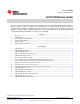
The high-current linearity correction circuit (refer to Figure 4) creates an error signal that is proportional to
input current I
1
by using R2, R3 and R4, and amplifier A5. Resistor R1 is used to properly level-shift the
resulting output signal. The signal at the output from amplifier A5 is then coupled to the input of amplifier
A4 in a manner that subtracts the error signal from the output of the EVM, V
OUT
.
Figure 4. High-Current Linearity Correction Circuit
5
SBOU110–September 2011 LOG114EVM User Guide
Submit Documentation Feedback
Copyright © 2011, Texas Instruments Incorporated