
Datasheet


Table Of Contents
- FEATURES
- APPLICATIONS
- DESCRIPTION
- Electrical Specifications
- Performance Benefits
- Absolute Maximum Ratings
- Operating Ratings
- Electrical Characteristics
- Typical Performance Characteristics
- Block Diagram
- Design Steps for the LMZ22005 Application
- ENABLE DIVIDER, RENT, RENB AND RENHSELECTION
- OUTPUT VOLTAGE SELECTION
- SOFT-START CAPACITOR SELECTION
- TRACKING SUPPLY DIVIDER OPTION
- CO SELECTION
- CIN SELECTION
- POWER DISSIPATION AND BOARD THERMAL REQUIREMENTS
- PC BOARD LAYOUT GUIDELINES
- Additional Features
- Typical Application Schematic Diagram
- Power Module SMT Guidelines
- Revision History
LMZ22005
SNVS686I –MARCH 2011–REVISED OCTOBER 2013
www.ti.com
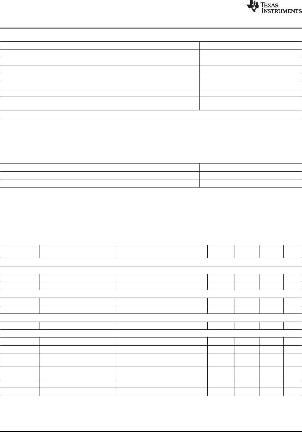
Absolute Maximum Ratings
(1)(2)
VIN to PGND -0.3V to 24V
EN, SYNC to AGND -0.3V to 5.5V
SS/TRK, FB to AGND -0.3V to 2.5V
AGND to PGND -0.3V to 0.3V
Junction Temperature 150°C
Storage Temperature Range -65°C to 150°C
ESD Susceptibility
(3)
± 2 kV
Peak Reflow Case Temperature 245°C
(30 sec)
For soldering specifications, refer to the following document: www.ti.com/lit/snoa549c
(1) Absolute Maximum Ratings are limits beyond which damage to the device may occur. Operating Ratings are conditions under which
operation of the device is intended to be functional. For guaranteed specifications and test conditions, see the Electrical Characteristics.
(2) If Military/Aerospace specified devices are required, please contact the Texas Instruments Sales Office/ Distributors for availability and
specifications.
(3) The human body model is a 100pF capacitor discharged through a 1.5 kΩ resistor into each pin. Test method is per JESD-22-114.
Operating Ratings
(1)
VIN 6V to 20V
EN, SYNC 0V to 5.0V
Operation Junction Temperature −40°C to 125°C
(1) Absolute Maximum Ratings are limits beyond which damage to the device may occur. Operating Ratings are conditions under which
operation of the device is intended to be functional. For guaranteed specifications and test conditions, see the Electrical Characteristics.
Electrical Characteristics
Limits in standard type are for T
J
= 25°C only; limits in boldface type apply over the junction temperature (T
J
) range of -40°C
to +125°C. Minimum and Maximum limits are guaranteed through test, design or statistical correlation. Typical values
represent the most likely parametric norm at T
J
= 25°C, and are provided for reference purposes only. Unless otherwise
stated the following conditions apply: V
IN
= 12V, Vout = 3.3V
Min Typ Max
Symbol Parameter Conditions Units
(1) (2) (1)
SYSTEM PARAMETERS
Enable Control
V
EN
EN threshold trip point V
EN
rising 1.10 1.279 1.458 V
V
EN-HYS
EN hysteresis V
EN
> 1.279V 21 µA
Soft-Start
I
SS
SS source current V
SS
= 0V 40 50 60 µA
t
SS
Internal soft-start interval 1.6 msec
Current Limit
I
CL
Current limit threshold d.c. average 5.4 A
Internal Switching Oscillator
f
osc
Free-running oscillator frequency Sync input connected to ground. 711 812 914 kHz
f
sync
Synchronization range 650 950 kHz
V
IL-sync
Synchronization logic zero Relative to AGND 0.4 V
amplitude
V
IH-sync
Synchronization logic one Relative to AGND 1.5 V
amplitude
Sync
d.c
. Synchronization duty cycle range 15 50 85 %
D
max
Maximum Duty Factor 83 %
(1) Min and Max limits are 100% production tested at 25°C. Limits over the operating temperature range are guaranteed through correlation
using Statistical Quality Control (SQC) methods. Limits are used to calculate Average Outgoing Quality Level (AOQL).
(2) Typical numbers are at 25°C and represent the most likely parametric norm.
4 Submit Documentation Feedback Copyright © 2011–2013, Texas Instruments Incorporated
Product Folder Links: LMZ22005