
Datasheet


Table Of Contents
- FEATURES
- APPLICATIONS
- DESCRIPTION
- Electrical Specifications
- Performance Benefits
- Absolute Maximum Ratings
- Operating Ratings
- Electrical Characteristics
- Typical Performance Characteristics
- Block Diagram
- Design Steps for the LMZ22005 Application
- ENABLE DIVIDER, RENT, RENB AND RENHSELECTION
- OUTPUT VOLTAGE SELECTION
- SOFT-START CAPACITOR SELECTION
- TRACKING SUPPLY DIVIDER OPTION
- CO SELECTION
- CIN SELECTION
- POWER DISSIPATION AND BOARD THERMAL REQUIREMENTS
- PC BOARD LAYOUT GUIDELINES
- Additional Features
- Typical Application Schematic Diagram
- Power Module SMT Guidelines
- Revision History
PGND/EP
Connect to AGND
5
FB
6
SS/TRK
3
EN
1
VIN
2
SYNC
4
AGND
7
VOUT
V
IN
C
IN
22 PF
Enable
R
FBT
See Table
C
SS
0.47 PF
R
FBB
See Table
Co
220 PF
LMZ22005
VOUT
SS/TRK
SYNC
FB
VIN
EN
PGND
V
OUT
@ 5A
5V 5.62k 1.07k 9...20V
V
OUT
R
FBT
R
FBB
V
IN
Range
3.3V 3.32k 1.07k 7...20V
2.5V 2.26k 1.07k 6...20V
1.8V 1.87k 1.50k 6...20V
1.5V 1.00k 1.13k 6...20V
1.2V 1.07k 2.05k 6...20V
0.8V 0 8.06K 6...20V
AGND
6V 15.4k 2.37k 10...20V
1.0V 1.62k 6.49k 6...20V
LMZ22005
www.ti.com
SNVS686I –MARCH 2011–REVISED OCTOBER 2013
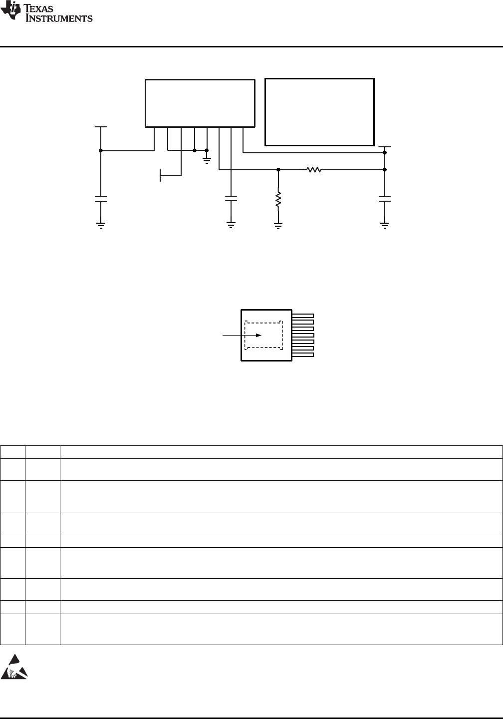
Simplified Application Schematic
Connection Diagram
Figure 2. Top View
7-Lead PFM
Pin Descriptions
Pin Name Description
1 VIN Supply input — Nominal operating range is 6V to 20V . A small amount of internal capacitance is contained within the
package assembly. Additional external input capacitance is required between this pin and exposed pad (PGND).
2 SYNC Sync Input — Apply a CMOS logic level square wave whose frequency is between 650 kHz and 950 kHz to synchronize
the PWM operating frequency to an external frequency source. When not using synchronization connect to ground. The
module free running PWM frequency is 812 kHz (Typ)
3 EN Enable — Input to the precision enable comparator. Rising threshold is 1.279V typical. Once the module is enabled, a 20
uA source current is internally activated to accommodate programmable hysteresis.
4 AGND Analog Ground — Reference point for all stated voltages. Must be externally connected to EP/PGND.
5 FB Feedback — Internally connected to the regulation, over-voltage, and short-circuit comparators. The regulation reference
point is 0.796V at this input pin. Connect the feedback resistor divider between the output and AGND to set the output
voltage.
6 SS/TRK Soft-Start/Track — To extend the 1.6 mSec internal soft-start connect an external soft start capacitor. For tracking connect
to an external resistive divider connected to a higher priority supply rail. See applications section.
7 VOUT Output Voltage — Output from the internal inductor. Connect the output capacitor between this pin and exposed pad.
EP PGND Exposed Pad / Power Ground Electrical path for the power circuits within the module. — NOT Internally connected to
AGND / pin 4. Used to dissipate heat from the package during operation. Must be electrically connected to pin 4 external
to the package.
These devices have limited built-in ESD protection. The leads should be shorted together or the device placed in conductive foam
during storage or handling to prevent electrostatic damage to the MOS gates.
Copyright © 2011–2013, Texas Instruments Incorporated Submit Documentation Feedback 3
Product Folder Links: LMZ22005