
Datasheet


LMV431, LMV431A, LMV431B
www.ti.com
SNVS041F –MAY 2004–REVISED MAY 2005
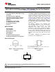
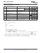
Figure 6. Test Circuit for Off-State Current
These devices have limited built-in ESD protection. The leads should be shorted together or the device placed in conductive foam
during storage or handling to prevent electrostatic damage to the MOS gates.
ABSOLUTE MAXIMUM RATINGS
(1)(2)
Storage Temperature Range −65°C to +150°C
Operating Temperature Range Industrial (LMV431AI, LMV431I) −40°C to +85°C
Commercial (LMV431AC, LMV431C, LMV431BC) 0°C to +70°C
Lead Temperature TO-92 Package/SOT-23 -5,-3 Package (Soldering, 10 sec.) 265°C
TO-92 0.78W
Internal Power Dissipation
(3)
SOT-23-5, -3 Package 0.28W
Cathode Voltage 35V
Continuous Cathode Current −30 mA to +30mA
Reference Input Current range −.05mA to 3mA
(1) Absolute Maximum Ratings indicate limits beyond which damage to the device may occur. Electrical specifications do not apply when
operating the device beyond its rated operating conditions.
(2) If Military/Aerospace specified devices are required, please contact the Texas Instruments Sales Office/ Distributors for availability and
specifications.
(3) Ratings apply to ambient temperature at 25°C. Above this temperature, derate the TO-92 at 6.2 mW/°C, and the SOT-23-5 at 2.2
mW/°C. See derating curve in Operating Condition section..
OPERATING CONDITIONS
Cathode Voltage V
REF
to 30V
Cathode Current 0.1 mA to 15mA
Temperature range LMV431AI −40°C ≤ T
A
≤ 85°C
Thermal Resistance (θ
JA
)
(1)
SOT-23-5, -3 Package 455 °C/W
TO-92 Package 161 °C/W
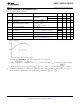
Derating Curve (Slope = −1/θ
JA
)
(1) T
J Max
= 150°C, T
J
= T
A
+ (θ
JA
P
D
), where P
D
is the operating power of the device.
Copyright © 2004–2005, Texas Instruments Incorporated Submit Documentation Feedback 3
Product Folder Links: LMV431 LMV431A LMV431B