
Datasheet


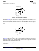
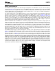
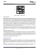

Table Of Contents
AMP Z
OUT
L2
L1
5V
5V
L4
L3
C1
C2
C3
L5
ADC Z
IN
R1
ADC V
IN
+
ADC V
IN
-
ADC V
CM
AMP V
OUT
-
AMP V
OUT
+
R2
LMH6514
SNOSB06A –JANUARY 2008–REVISED MARCH 2013
www.ti.com
Figure 51. Sample Filter
POWER SUPPLIES
As shown in Figure 52, the LMH6514 has a number of options for power supply connections on the output pins.
Pin 3 (V
CC
) is always connected. The output stage can be connected as shown in Figure 53, Figure 54, and
Figure 55. The supply voltage range for V
CC
is 4V to 5.25V. A 5V supply provides the best performance while
lower supplies will result in less power consumption. Power supply regulation of 2.5% or better is advised.
Of special note is that the digital circuits are powered from an internal supply voltage of 3.3V. The logic pins
should not be driven above the absolute maximum value of 3.6V. See the DIGITAL CONTROL section for
details.
20 Submit Documentation Feedback Copyright © 2008–2013, Texas Instruments Incorporated
Product Folder Links: LMH6514