
Datasheet
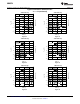


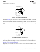
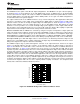

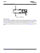
Table Of Contents
AMP R
OUT
680 nH
680 nH
5V
5V
390 nH
390 nH
3 pF
41 pF
27 nH
200
ADC C
IN
200:
3 pF
LMH6514
www.ti.com
SNOSB06A –JANUARY 2008–REVISED MARCH 2013
The output common mode voltage is not self biasing, it needs to be pulled up to the positive supply rail with
external inductors as shown in Figure 42. This gives the LMH6514 the capability for large signal swings with very
low distortion on a single 5V supply. The internal load resistors provide the LMH6514 with very consistent gain.
A unique internal architecture allows the LMH6514 to be driven by either a differential or single ended source. If
driving the LMH6514 single ended the unused input should be terminated to ground with a 0.01 µF capacitor.
Directly shorting the unused input to ground will disrupt the internal bias circuitry and will result in poor
performance.
Center Frequency is 140 MHz with a 20 MHz Bandwidth
Designed for 200Ω Impedance
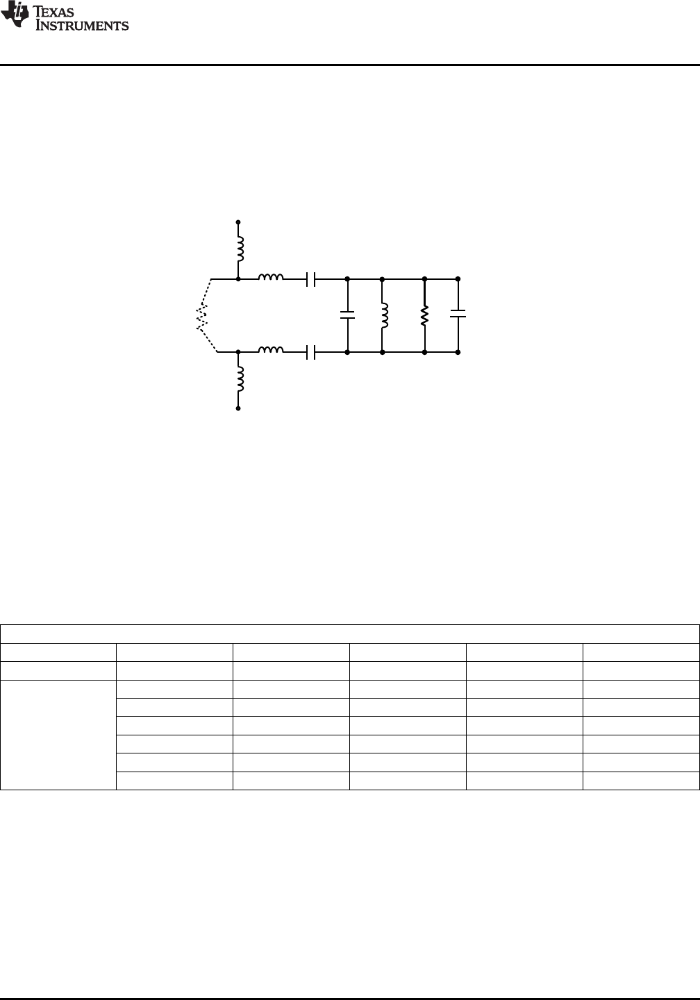
Figure 50. Bandpass Filter
ADC Noise Filter
Below is a filter schematic and a table of values for some common IF frequencies. The filter shown below offers
a good compromise between bandwidth, noise rejection and cost. This filter topology is the same as is used on
the ADC14V155KDRB High IF Receiver reference design board. This filter topology works best with the 12 and
14 bit sub-sampling analog to digital converters shown in the Table 2 table.
Table 1. Filter Component Values
Filter Component Values
Fc 75 MHz 140 MHz 170 MHz 250 MHz
BW 40 MHz 20 MHz 25 MHz Narrow Band
Components L1, L2 10 µH 10 µH 10 µH 10 µH
L3, L4 390 nH 39 0nH 560 nH —
C1, C2 10 pF 3 pF 1.4 pF 47 pF
C3 22 pF 41 pF 32 pF 11 pF
L5 220 nH 27 nH 30 nH 22 nH
R1, R2 100 200 100 499
Copyright © 2008–2013, Texas Instruments Incorporated Submit Documentation Feedback 19
Product Folder Links: LMH6514