
Datasheet


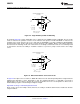
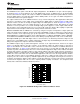
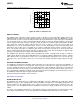

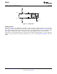
Table Of Contents
GAIN 1-5
5
LATCH
LMH6514
5V
V
IN
Z
IN
C
1
C
2
L
1
= 550 nH
C
1
= 36 pF
C
2
= 36 pF
L
1
SOURCE IMPEDANCE = 200:
f = 100 MHz
Z
AMP
= (150 ± j0):
Z
IN
= (202 ± j0.5):
Z
AMP
GAIN 1-5
5
LATCH
LMH6514
5V
V
IN
Z
IN
C
1
C
2
C
3
C
3
= 22 pF
L
1
= 169 nH
C
1
= 1 nF
C
2
= 1 nF
L
1
SOURCE IMPEDANCE = 50:
f = 100 MHz
Z
AMP
= (150 ± j0):
Z
IN
= (50 ± j1):
Z
AMP
LMH6514
SNOSB06A –JANUARY 2008–REVISED MARCH 2013
www.ti.com
Figure 46. Single Ended Input with LC Matching
As shown in Figure 46 a single ended 50Ω source is matched to the LMH6514 input at 100 MHz. The loss in this
circuit is related to the parasitic resistance in the inductor and capacitor and the bandwidth is related to the
loaded Q of the circuit. Since the Q, at 1.4 is quite low, the bandwidth is very wide. (59 MHz 0.3 dB bandwidth).
The input match of this circuit is quite good. It converts the Z
AMP
of the amplifier, which is (150 +j0)Ω to (50+j1)Ω.
The benefit of LC matching circuits over a transformer is the ability to match ratios that are not commonly found
on transformers and also the ability to neutralize reactance to present a purely resistive load to the voltage
source.
Figure 47. Differential 200Ω LC Conversion Circuit
In Figure 47 the input source resistance is 200Ω differential. Here the desired input impedance is higher than the
amplifier input impedance, and is differential as well. The amplifier impedance of (150–j0)Ω is increased to
(202–j0.5)Ω. For an easy way to calculate the L and C circuit values there are several options for online tools or
down-loadable programs. The following tool might be helpful.
http://www.circuitsage.com/matching/matcher2.html
Excel can also be used for simple circuits; however, the “Analysis ToolPak” add-in must be installed to calculate
complex numbers.
16 Submit Documentation Feedback Copyright © 2008–2013, Texas Instruments Incorporated
Product Folder Links: LMH6514