
Datasheet


2.0 Modes of Operation
The LMF100 is a switched capacitor (sampled data) filter. To
fully describe its transfer functions, a time domain analysis is
appropriate. Since this is cumbersome, and since the
LMF100 closely approximates continuous filters, the follow-
ing discussion is based on the well-known frequency do-
main. Each LMF100 can produce two full 2nd order func-
tions. See
Table 1
for a summary of the characteristics of the
various modes.
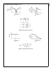
MODE 1: Notch 1, Bandpass, Lowpass Outputs:
f
notch
=f
0
(See
Figure 7
)
MODE 1a: Non-Inverting BP, LP (See
Figure 8
)
Note: V
IN
should be driven from a low impedance (
<
1kΩ) source.
DS005645-11
FIGURE 7. MODE 1
DS005645-4
FIGURE 8. MODE 1a
LMF100
www.national.com13