
Datasheet


1.0 Definitions of Terms
f
CLK
: the frequency of the external clock signal applied to pin
10 or 11.
f
0
: center frequency of the second order function complex
pole pair. f
0
is measured at the bandpass outputs of the
LMF100, and is the frequency of maximum bandpass gain.
(
Figure 1
).
f
notch
: the frequency of minimum (ideally zero) gain at the
notch outputs.
f
z
: the center frequency of the second order complex zero
pair, if any. If f
z
is different from f
0
and if Q
z
is high, it can be
observed as the frequency of a notch at the allpass output.
(
Figure 13
).
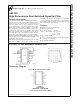
Q: “quality factor” of the 2nd order filter. Q is measured at the
bandpass outputs of the LMF100 and is equal to f
0
divided
by the −3 dB bandwidth of the 2nd order bandpass filter (
Fig-
ure 1
). The value of Q determines the shape of the 2nd order
filter responses as shown in
Figure 6
.
Q
z
: the quality factor of the second order complex zero pair,
if any. Q
Z
is related to the allpass characteristic, which is
written:
where Q
Z
= Q for an all-pass response.
H
OBP
: the gain (in V/V) of the bandpass output at f = f
0
.
H
OLP
: the gain (in V/V) of the lowpass output as f
→
0Hz
(
Figure 2
).
H
OHP
: the gain (in V/V) of the highpass output as f
→
f
CLK
/2
(
Figure 3
).
H
ON
: the gain (in V/V) of the notch output as f
→
0 Hz and as
f
→
f
CLK
/2, when the notch filter has equal gain above and
below the center frequency (
Figure 4
). When the
low-frequency gain differs from the high-frequency gain, as
in modes 2 and 3a (
Figure 10
and
Figure 12
), the two quan-
tities below are used in place of H
ON
.
H
ON1
: the gain (in V/V) of the notch output as f
→
0 Hz.
H
ON2
: the gain (in V/V) of the notch output as f
→
f
CLK
/2.
DS005645-19
(a)
DS005645-20
(b)
FIGURE 1. 2nd-Order Bandpass Response
LMF100
www.national.com9