
Datasheet
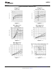
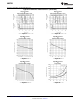
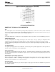
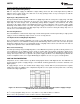
Table Of Contents
- FEATURES
- Applications
- DESCRIPTION
- Absolute Maximum Ratings
- Operating Ratings
- 2.7V Electrical Characteristics
- 5.0V and 15.0V Electrical Characteristics
- Leakage Characteristics
- AC Electrical Characteristics
- Typical Performance Characteristics
- Application Information
- Revision History
LMC7221
SNOS748E –SEPTEMBER 1999–REVISED MARCH 2013
www.ti.com
5.0V and 15.0V Electrical Characteristics (continued)
Unless otherwise specified, all limits ensured for T
J
= 25°C, V
+
= 5.0V and 15V, V
−
= 0V, V
CM
= V
O
= V
+
/2. Boldface limits
apply at the temperature extremes.
Parameter Test Conditions LMC7221AI LMC7221BI Units
Typ
(1)
Limit
(2)
Limit
(2)
I
SC
Short Circuit Current Sinking
(4)
45 mA
(4) Limiting input pin current is only necessary for input voltages which exceed the absolute maximum input voltage rating.
Leakage Characteristics
T
J
= 25°C
Parameter Test Conditions LMC7221AI LMC7221BI Units
Typ
(1)
Limit
(2)
Limit
(2)
I
LEAKAGE
Output Leakage Current V
+
= 2.7V
V
IN
(+) = 0.5V
0.1 500 500 nA
V
IN
(−) = 0V
V
OUT
= 15V
(1) Typical values represent the most likely parametric norm as determined at the time of characterization. Actual typical values may vary
over time and will also depend on the application and configuration. The typical values are not tested and are not ensured on shipped
production material.
(2) All limits are specified by testing or statistical analysis.
AC Electrical Characteristics
Unless otherwise specified, all limits ensured for T
J
= 25°C, V
+
= 5V, V
−
= 0V, V
CM
= V
O
= V
+
/2. Boldface limits apply at the
temperature extreme.
Parameter Test Conditions LMC7221AI LMC7221BI Units
Typ
(1)
Limit
(2)
Limit
(2)
t
rise
Rise Time f = 10 kHz, C
L
= 50 pF,
(3)
0.3
μs
Overdrive = 10 mV, 5 kΩ Pullup
t
fall
Fall Time f = 10 kHz, C
L
= 50 pF,
(3)
0.3
μs
Overdrive = 10 mV, 5 kΩ Pullup
t
PHL
Propagation Delay f = 10 kHz, C
L
= 50 pF, 10 mV 10
μs
(High to Low)
(4)
5 kΩ Pullup
(3)
100 mV 4
V
+
= 2.7V, f = 10 kHz, 10 mV 10
μs
C
L
= 50 pF, 5 kΩ Pullup
(3)
100 mV 4
t
PLH
Propagation Delay f = 10 kHz, C
L
= 50 pF, 10 mV 6
μs
(Low to High)
(4)
5 kΩ Pullup
(3)
100 mV 4
V
+
= 2.7V, f = 10 kHz, 10 mV 7
μs
C
L
= 50 pF, 5 kΩ Pullup
(3)
100 mV 4
(1) Typical values represent the most likely parametric norm as determined at the time of characterization. Actual typical values may vary
over time and will also depend on the application and configuration. The typical values are not tested and are not ensured on shipped
production material.
(2) All limits are specified by testing or statistical analysis.
(3) Do not short circuit the output to V
+
when V
+
is greater than 12V or reliability will be adversely affected.
(4) Input offset voltage average drift is calculated by dividing the accelerated operating life V
OS
drift by the equivalent operational time. This
represents worst case input conditions and includes the first 30 days of drift.
4 Submit Documentation Feedback Copyright © 1999–2013, Texas Instruments Incorporated
Product Folder Links: LMC7221