
Datasheet


LMC6762
SNOS739D –JULY 1997–REVISED MARCH 2013
www.ti.com
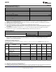
5.0V and 15.0V Electrical Characteristics (continued)
Unless otherwise specified, all limits ensured for T
J
= 25°C, V
+
= 5.0V and 15.0V, V
−
= 0V, V
CM
= V
+
/2. Boldface limits apply
at the temperature extremes.
LMC6762AI LMC6762BI
Symbol Parameter Conditions Typ
(1)
Units
Limit
(2)
Limit
(1)
V
OL
Output Voltage Low V
+
= 5V 0.2 0.4 0.4 V
I
LOAD
= 5 mA 0.55 0.55 max
V
+
= 15V 0.2 0.4 0.4 V
I
LOAD
= 5 mA 0.55 0.55 max
I
S
Supply Current For Both Comparators 12 20 20 μA
(Output Low) 25 25 max
I
SC
Short Circuit Current Sourcing 30 mA
Sinking, V
O
= 12V
(4)
45
(4) Do not short circuit output to V
+
, when V
+
is greater than 12V or reliability will be adversely affected.
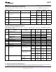
AC Electrical Characteristics
Unless otherwise specified, all limits ensured for T
J
= 25°C, V
+
= 5V, V
−
= 0V, V
CM
= V
O
= V
+
/2. Boldface limits apply at the
temperature extreme.
Symbol Parameter Conditions Typ
(1)
LMC6762AI LMC6762BI Units
Limit
(2)
Limit
(2)
t
RISE
Rise Time f = 10 kHz, C
L
= 50 pF, 0.3 μs
Overdrive = 10 mV
(3)(4)
t
FALL
Fall Time f = 10 kHz, C
L
= 50 pF, 0.3 μs
Overdrive = 10 mV
(3)(4)
t
PHL
Propagation Delay f = 10 kHz, Overdrive = 10 mV 10 μs
(High to Low) C
L
= 50 pF
(3)(4)
Overdrive = 100 mV 4 μs
V
+
= 2.7V, Overdrive = 10 mV 10 μs
f = 10 kHz,
C
L
= 50 pF
(3)(4)
Overdrive = 100 mV 4 μs
t
PLH
Propagation Delay f = 10 kHz, Overdrive = 10 mV 6 μs
(Low to High) C
L
= 50 pF
(3)(4)
Overdrive = 100 mV 4 μs
V
+
= 2.7V, Overdrive = 10 mV 7 μs
f = 10 kHz,
C
L
= 50 pF
(3)(4)
Overdrive = 100 mV 4 μs
(1) Typical Values represent the most likely parametric norm.
(2) All limits are specified by testing or statistical analysis.
(3) C
L
includes the probe and jig capacitance.
(4) The rise and fall times are measured with a 2V input step. The propagation delays are also measured with a 2V input step.
4 Submit Documentation Feedback Copyright © 1997–2013, Texas Instruments Incorporated
Product Folder Links: LMC6762