
Datasheet


LMC6572, LMC6574
www.ti.com
SNOS707D –DECEMBER 1996–REVISED MARCH 2013
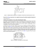
Figure 31. LMC6574/2 Noninverting Gain of 10 Amplifier, Compensated to Handle Capacitive Loads
In the circuit of Figure 31, R1 and C1 serve to counteract the loss of phase margin by feeding the high frequency
component of the output signal back to the amplifier's inverting input, thereby preserving phase margin in the
overall feedback loop.
PRINTED-CIRCUIT-BOARD LAYOUT FOR HIGH-IMPEDANCE WORK
It is generally recognized that any circuit which must operate with less than 1000 pA of leakage current requires
special layout of the PC board. When one wishes to take advantage of the ultra-low bias current of the
LMC6574/2, typically less than 20 fA, it is essential to have an excellent layout. Fortunately, the techniques of
obtaining low leakages are quite simple. First, the user must not ignore the surface leakage of the PC board,
even though it may sometimes appear acceptably low, because under conditions of high humidity or dust or
contamination, the surface leakage will be appreciable.
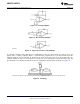
To minimize the effect of any surface leakage, lay out a ring of foil completely surrounding the LMC6574/2's
inputs and the terminals of capacitors, diodes, conductors, resistors, relay terminals, etc. connected to the op-
amp's inputs, as in Figure 32. To have a significant effect, guard rings should be placed on both the top and
bottom of the PC board. This PC foil must then be connected to a voltage which is at the same voltage as the
amplifier inputs, since no leakage current can flow between two points at the same potential. For example, a PC
board trace-to-pad resistance of 10
12
Ω, which is normally considered a very large resistance, could leak 5 pA if
the trace were a 5V bus adjacent to the pad of the input. This would cause a 250 times degradation from the
LMC6574/2's actual performance. However, if a guard ring is held within 5 mV of the inputs, then even a
resistance of 10
11
Ω would cause only 0.05 pA of leakage current. See Figure 35 for typical connections of guard
rings for standard op-amp configurations.
Figure 32. Example of Guard Ring in P.C. Board Layout
Copyright © 1996–2013, Texas Instruments Incorporated Submit Documentation Feedback 11
Product Folder Links: LMC6572 LMC6574