
Datasheet


Table Of Contents
- FEATURES
- APPLICATIONS
- DESCRIPTION
- Absolute Maximum Ratings
- Operating Ratings
- DC Electrical Characteristics
- AC Electrical Characteristics
- DC Electrical Characteristics
- AC Electrical Characteristics
- Typical Performance Characteristics
- Application Information
- AMPLIFIER TOPOLOGY
- INPUT COMMON-MODE VOLTAGE RANGE
- RAIL-TO-RAIL OUTPUT
- CAPACITIVE LOAD TOLERANCE
- COMPENSATING FOR INPUT CAPACITANCE
- PRINTED-CIRCUIT-BOARD LAYOUT FOR HIGH-IMPEDANCE WORK
- OFFSET VOLTAGE ADJUSTMENT
- UPGRADING APPLICATIONS
- DATA ACQUISITION SYSTEMS
- INSTRUMENTATION CIRCUITS
- SPICE MACROMODEL
- Typical Single-Supply Applications
- Revision History
LMC6482
www.ti.com
SNOS674D –NOVEMBER 1997–REVISED MARCH 2013
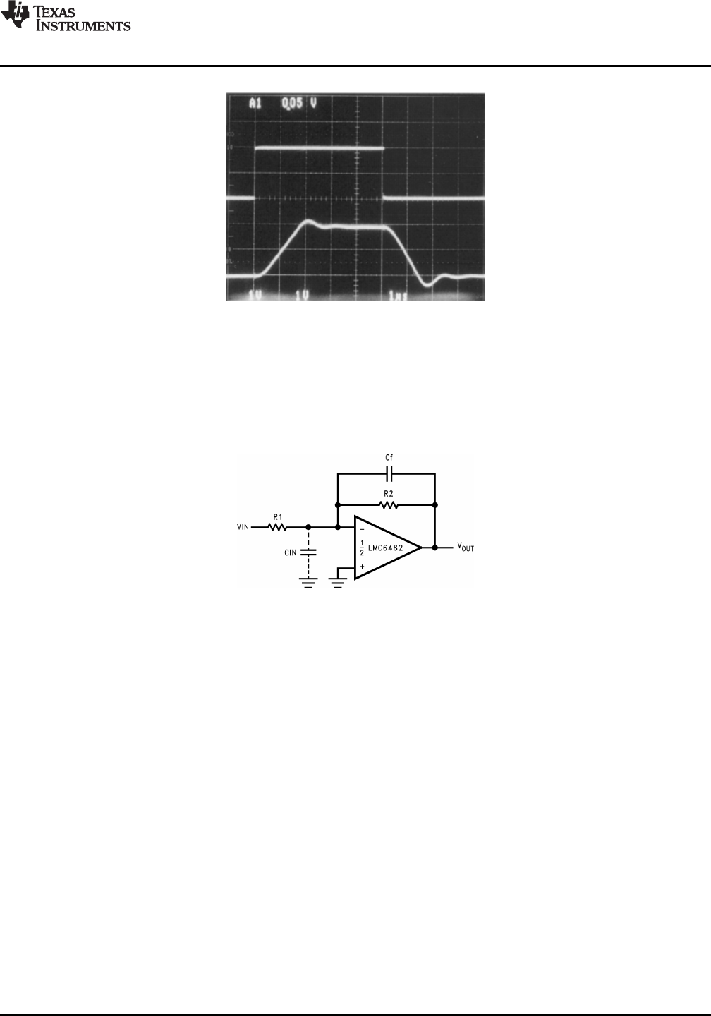
Figure 62. Pulse Response of
LMC6482 Circuit in Figure 61
COMPENSATING FOR INPUT CAPACITANCE
It is quite common to use large values of feedback resistance with amplifiers that have ultra-low input current,
like the LMC6482. Large feedback resistors can react with small values of input capacitance due to transducers,
photo diodes, and circuits board parasitics to reduce phase margins.
Figure 63. Canceling the Effect of Input Capacitance
Copyright © 1997–2013, Texas Instruments Incorporated Submit Documentation Feedback 19
Product Folder Links: LMC6482