
Datasheet


LMC6462, LMC6464
SNOS725D –MAY 1999–REVISED MARCH 2013
www.ti.com
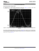
In Figure 52 Figure 53, R
I
limits current into the amplifier since excess current can be caused by the input
voltage exceeding the supply voltage.
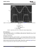
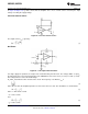
Precision Current Source
Figure 54. Precision Current Source
The output current I
OUT
is given by:
(3)
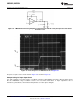
Oscillators
Figure 55. 1 Hz Square-Wave Oscillator
For single supply 5V operation, the output of the circuit will swing from 0V to 5V. The voltage divider set up R
2
,
R
3
and R
4
will cause the non-inverting input of the LMC6462 to move from 1.67V (⅓ of 5V) to 3.33V (⅔ of 5V).
This voltage behaves as the threshold voltage.
R
1
and C
1
determine the time constant of the circuit. The frequency of oscillation, f
OSC
is
(4)
where Δt is the time the amplifier input takes to move from 1.67V to 3.33V. The calculations are shown below.
(5)
where τ = RC = 0.68 seconds
→t
1
= 0.27 seconds.
and
(6)
→t
2
= 0.75 seconds
20 Submit Documentation Feedback Copyright © 1999–2013, Texas Instruments Incorporated
Product Folder Links: LMC6462 LMC6464