
Datasheet


LMC6061
SNOS648D –NOVEMBER 1994–REVISED MARCH 2013
www.ti.com
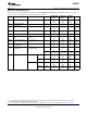
DC Electrical Characteristics (continued)
Unless otherwise specified, all limits ensured for T
J
= 25°C. Boldface limits apply at the temperature extremes. V
+
= 5V, V
−
=
0V, V
CM
= 1.5V, V
O
= 2.5V and R
L
> 1M unless otherwise specified.
LMC6061AM LMC6061AI LMC6061I
Symbol Parameter Conditions Typ
(1)
Units
Limit
(2)
Limit
(2)
Limit
(2)
V
O
Output Swing V
+
= 5V 4.995 4.990 4.990 4.950 V
R
L
= 100 kΩ to 2.5V
4.970 4.980 4.925 Min
0.005 0.010 0.010 0.050 V
0.030 0.020 0.075 Max
V
+
= 5V 4.990 4.975 4.975 4.950 V
R
L
= 25 kΩ to 2.5V
4.955 4.965 4.850 Min
0.010 0.020 0.020 0.050 V
0.045 0.035 0.150 Max
V
+
= 15V 14.990 14.975 14.975 14.950 V
R
L
= 100 kΩ to 7.5V
14.955 14.965 14.925 Min
0.010 0.025 0.025 0.050 V
0.050 0.035 0.075 Max
V
+
= 15V 14.965 14.900 14.900 14.850 V
R
L
= 25 kΩ to 7.5V
14.800 14.850 14.800 Min
0.025 0.050 0.050 0.100 V
0.200 0.150 0.200 Max
I
O
Output Current Sourcing, V
O
= 0V 22 16 16 13 mA
V
+
= 5V
8 10 8 Min
Sinking, V
O
= 5V 21 16 16 16 mA
7 8 8 Min
I
O
Output Current Sourcing, V
O
= 0V 25 15 15 15 mA
V
+
= 15V
9 10 10 Min
Sinking, V
O
= 13V
(4)
26 20 20 20 mA
7 8 8 Min
I
S
Supply Current V
+
= +5V, V
O
= 1.5V 20 24 24 32 μA
35 32 40 Max
V
+
= +15V, V
O
= 7.5V 24 30 30 40 μA
40 38 48 Max
(4) Do not connect output to V
+
, when V
+
is greater than 13V or reliability witll be adversely affected.
AC Electrical Characteristics
Unless otherwise specified, all limits ensured for T
J
= 25°C, Boldface limits apply at the temperature extremes. V
+
= 5V, V
−
=
0V, V
CM
= 1.5V, V
O
= 2.5V and R
L
> 1M unless otherwise specified.
LMC6061AM LMC6061AI LMC6061I
Symbol Parameter Conditions Typ
(1)
Units
Limit
(2)
Limit
(2)
Limit
(2)
SR Slew Rate See
(3)
35 20 20 15 V/ms
8 10 7 Min
GBW Gain-Bandwidth Product 100 kHz
θ
m
Phase Margin 50 Deg
e
n
Input-Referred Voltage Noise F = 1 kHz 83 nV/√Hz
i
n
Input-Referred Current Noise F = 1 kHz 0.0002 pA/√Hz
(1) Typical values represent the most likely parametric norm.
(2) All limits are specified by testing or statistical analysis.
(3) V
+
= 15V. Connected as Voltage Follower with 10V step input. Number specified is the slower of the positive and negative slew rates.
4 Submit Documentation Feedback Copyright © 1994–2013, Texas Instruments Incorporated
Product Folder Links: LMC6061