
Datasheet


LMC6035, LMC6035-Q1, LMC6036
SNOS875G –JANUARY 2000–REVISED APRIL 2013
www.ti.com
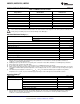
DC Electrical Characteristics (continued)
Unless otherwise specified, all limits ensured for T
J
= 25°C, V
+
= 2.7V, V
−
= 0V, V
CM
= 1.0V, V
O
= 1.35V and R
L
> 1MΩ.
Boldface limits apply at the temperature extremes.
LMC6035I/LMC6036I
Parameter Test Conditions Units
Min
(1)
Typ
(2)
Max
(1)
V
O
Output Swing V
+
= 2.7V 2.0 2.5
R
L
= 600Ω to 1.35V 1.8
V
0.2 0.5
0.7
V
+
= 2.7V 2.4 2.62
R
L
= 2kΩ to 1.35V 2.2
V
0.07 0.2
0.4
V
+
= 15V 13.5 14.5
R
L
= 600Ω to 7.5V 13.0
V
0.36 1.25
1.50
V
+
= 15V, 14.2 14.8
R
L
= 2 kΩ to 7.5V 13.5
V
0.12 0.4
0.5
I
O
Output Current V
O
= 0V Sourcing 4 8
3
mA
V
O
= 2.7V Sinking 3 5
2
I
S
Supply Current LMC6035 for Both Amplifiers 0.65 1.6
V
O
= 1.35V 1.9
mA
LMC6036 for All Four Amplifiers 1.3 2.7
V
O
= 1.35V 3.0
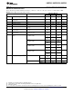
AC Electrical Characteristics
Unless otherwise specified, all limits ensured for T
J
= 25°C, V
+
= 2.7V, V
−
= 0V, V
CM
= 1.0V, V
O
= 1.35V and R
L
> 1 MΩ.
Boldface limits apply at the temperature extremes.
Parameter Test Conditions Typ
(1)
Units
SR Slew Rate See
(2)
1.5 V/μs
GBW Gain Bandwidth Product V
+
= 15V 1.4 MHz
θ
m
Phase Margin 48 °
G
m
Gain Margin 17 dB
Amp-to-Amp Isolation See
(3)
130 dB
e
n
Input-Referred Voltage Noise f = 1kHz 27 nV/√Hz
V
CM
= 1V
i
n
Input Referred Current Noise f = 1kHz 0.2 fA/√Hz
THD Total Harmonic Distortion f = 10kHz, A
V
= −10 0.01 %
R
L
= 2kΩ, V
O
= 8 V
PP
V
+
= 10V
(1) Typical Values represent the most likely parametric norm or one sigma value.
(2) V
+
= 15V. Connected as voltage follower with 10V step input. Number specified is the slower of the positive and negative slew rates.
(3) Input referred, V
+
= 15V and R
L
= 100kΩ connected to 7.5V. Each amp excited in turn with 1kHz to produce V
O
= 12 V
PP
.
4 Submit Documentation Feedback Copyright © 2000–2013, Texas Instruments Incorporated
Product Folder Links: LMC6035 LMC6035-Q1 LMC6036