
Datasheet


LMC6035, LMC6035-Q1, LMC6036
www.ti.com
SNOS875G –JANUARY 2000–REVISED APRIL 2013
Low-Pass Frequency Scaling Procedure
The actual component values represented in bold of Figure 47 were obtained with the following scaling
procedure:
1. First determine the frequency scaling factor (FSF) for the desired cutoff frequency. Choosing f
c
at 3kHz,
provides the following FSF computation:
– FSF = 2π x 3kHz
(desired cutoff freq.)
= 18.84 x 10
3
2. Then divide all of the normalized capacitor values by the FSF as follows: C1' = C
(Normalized)
/FSF C1' =
0.707/18.84 x 10
3
= 37.93 x 10
−6
C2' = 1.414/18.84 x 10
3
= 75.05 x 10
−6
(C1' and C2': prior to
impedance scaling)
3. Last, choose an impedance scaling factor (Z). This Z factor can be calculated from a standard value for C2.
Then Z can be used to determine the remaining component values as follows:
Z = C2'/C2
(chosen)
= 75.05 x 10
−6
/6.8nF = 8.4k
C1 = C1'/Z = 37.93 x 10
−6
/8.4k = 4.52nF
(Standard capacitor value chosen for C1 is 4.7nF ) R1 = R1
(normalized)
x Z = 1Ω x 8.4k = 8.4kΩ R2 =
R2
(normalized)
x Z = 1Ω x 8.4k = 8.4kΩ
(Standard value chosen for R1 and R2 is 8.45kΩ )
High Pass Active Filter
The previous low-pass filter circuit of Figure 47 converts to a high-pass active filter per Figure 48.
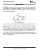
Figure 48. 2 Pole, 300Hz, Sallen and Key, High-Pass Filter
High-Pass Frequency Scaling Procedure
Choose a standard capacitor value and scale the impedances in the circuit according to the desired cutoff
frequency (300Hz) as follows: C = C1 = C2 Z = 1 Farad/C
(chosen)
x 2π x (desired cutoff freq.) = 1
Farad/6.8nF x 2π x 300 Hz = 78.05k
R1 = Z x R1
(normalized)
= 78.05k x (1/0.707) = 110.4kΩ
(Standard value chosen for R1 is 110kΩ )
R2 = Z x R2
(normalized)
= 78.05k x (1/1.414) = 55.2kΩ
(Standard value chosen for R1 is 54.9kΩ )
Dual Amplifier Bandpass Filter
The dual amplifier bandpass (DABP) filter features the ability to independently adjust f
c
and Q. In most other
bandpass topologies, the f
c
and Q adjustments interact with each other. The DABP filter also offers both low
sensitivity to component values and high Qs. The following application of Figure 49, provides a 1kHz center
frequency and a Q of 100.
Copyright © 2000–2013, Texas Instruments Incorporated Submit Documentation Feedback 15
Product Folder Links: LMC6035 LMC6035-Q1 LMC6036