
Datasheet


Table Of Contents
- FEATURES
- Applications
- Key Specifications
- DESCRIPTION
- Absolute Maximum Ratings
- Operating Ratings
- Temperature-to-Digital Converter Characteristics
- Logic Electrical Characteristics
- SMBus DIGITAL SWITCHING CHARACTERISTICS
- Functional Description
- CONVERSION SEQUENCE
- THE ALERT OUTPUT
- T_CRIT_A OUTPUT and T_CRIT LIMIT
- POWER ON RESET DEFAULT STATES
- SMBus INTERFACE
- TEMPERATURE DATA FORMAT
- OPEN-DRAIN OUTPUTS
- DIODE FAULT DETECTION
- COMMUNICATING with the LM90
- SERIAL INTERFACE RESET
- DIGITAL FILTER
- Fault Queue
- One-Shot Register
- LM90 REGISTERS
- COMMAND REGISTER
- LOCAL and REMOTE TEMPERATURE REGISTERS (LT, RTHB, RTLB)
- STATUS REGISTER (SR)
- CONFIGURATION REGISTER
- CONVERSION RATE REGISTER
- LOCAL and REMOTE HIGH SETPOINT REGISTERS (LHS, RHSHB, and RHSLB)
- LOCAL and REMOTE LOW SETPOINT REGISTERS (LLS, RLSHB, and RLSLB)
- REMOTE TEMPERATURE OFFSET REGISTERS (RTOHB and RTOLB)
- LOCAL and REMOTE T_CRIT REGISTERS (RCS and LCS)
- T_CRIT HYSTERESIS REGISTER (TH)
- FILTER and ALERT CONFIGURE REGISTER
- MANUFACTURERS ID REGISTER
- DIE REVISION CODE REGISTER
- Application Hints
- Revision History
LM90
www.ti.com
SNIS126A –MAY 2004–REVISED MARCH 2013
THE ALERT OUTPUT
The LM90's ALERT pin is an active-low open-drain output that is triggered by a temperature conversion that is
outside the limits defined by the temperature setpoint registers. Reset of the ALERT output is dependent upon
the selected method of use. The LM90's ALERT pin is versatile and will accommodate three different methods of
use to best serve the system designer: as a temperature comparator, as a temperature based interrupt flag, and
as part of an SMBus ALERT system. The three methods of use are further described below. The ALERT and
interrupt methods are different only in how the user interacts with the LM90.
Each temperature reading (LT and RT) is associated with a T_CRIT setpoint register (LCS, RCS), a HIGH
setpoint register (LHS and RHS) and a LOW setpoint register (LLS and RLS). At the end of every temperature
reading, a digital comparison determines whether that reading is above its HIGH or T_CRIT setpoint or below its
LOW setpoint. If so, the corresponding bit in the STATUS REGISTER is set. If the ALERT mask bit is not high,
any bit set in the STATUS REGISTER, with the exception of Busy (D7) and OPEN (D2), will cause the ALERT
output to be pulled low. Any temperature conversion that is out of the limits defined by the temperature setpoint
registers will trigger an ALERT. Additionally, the ALERT mask bit in the Configuration register must be cleared to
trigger an ALERT in all modes.
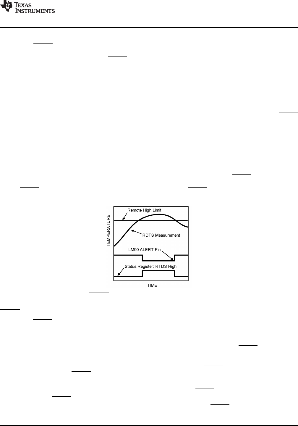
ALERT Output as a Temperature Comparator
When the LM90 is implemented in a system in which it is not serviced by an interrupt routine, the ALERT output
could be used as a temperature comparator. Under this method of use, once the condition that triggered the
ALERT to go low is no longer present, the ALERT is de-asserted (Figure 4). For example, if the ALERT output
was activated by the comparison of LT > LHS, when this condition is no longer true the ALERT will return HIGH.
This mode allows operation without software intervention, once all registers are configured during set-up. In order
for the ALERT to be used as a temperature comparator, bit D0 (the ALERT configure bit) in the FILTER and
ALERT CONFIGURE REGISTER (xBF) must be set high. This is not the power on default default state.
Figure 4. ALERT Comparator Temperature Response Diagram
ALERT Output as an Interrupt
The LM90's ALERT output can be implemented as a simple interrupt signal when it is used to trigger an interrupt
service routine. In such systems it is undesirable for the interrupt flag to repeatedly trigger during or before the
interrupt service routine has been completed. Under this method of operation, during a read of the STATUS
REGISTER the LM90 will set the ALERT mask bit (D7 of the Configuration register) if any bit in the STATUS
REGISTER is set, with the exception of Busy (D7) and OPEN (D2). This prevents further ALERT triggering until
the master has reset the ALERT mask bit, at the end of the interrupt service routine. The STATUS REGISTER
bits are cleared only upon a read command from the master (see Figure 5) and will be re-asserted at the end of
the next conversion if the triggering condition(s) persist(s). In order for the ALERT to be used as a dedicated
interrupt signal, bit D0 (the ALERT configure bit) in the FILTER and ALERT CONFIGURE REGISTER (xBF) must
be set low. This is the power on default state.
The following sequence describes the response of a system that uses the ALERT output pin as a interrupt flag:
1. Master Senses ALERT low
2. Master reads the LM90 STATUS REGISTER to determine what caused the ALERT
3. LM90 clears STATUS REGISTER, resets the ALERT HIGH and sets the ALERT mask bit (D7 in the
Copyright © 2004–2013, Texas Instruments Incorporated Submit Documentation Feedback 9
Product Folder Links: LM90