
Datasheet


Table Of Contents
- FEATURES
- Applications
- Key Specifications
- DESCRIPTION
- Absolute Maximum Ratings
- Operating Ratings
- Temperature-to-Digital Converter Characteristics
- Logic Electrical Characteristics
- SMBus DIGITAL SWITCHING CHARACTERISTICS
- Functional Description
- CONVERSION SEQUENCE
- THE ALERT OUTPUT
- T_CRIT_A OUTPUT and T_CRIT LIMIT
- POWER ON RESET DEFAULT STATES
- SMBus INTERFACE
- TEMPERATURE DATA FORMAT
- OPEN-DRAIN OUTPUTS
- DIODE FAULT DETECTION
- COMMUNICATING with the LM90
- SERIAL INTERFACE RESET
- DIGITAL FILTER
- Fault Queue
- One-Shot Register
- LM90 REGISTERS
- COMMAND REGISTER
- LOCAL and REMOTE TEMPERATURE REGISTERS (LT, RTHB, RTLB)
- STATUS REGISTER (SR)
- CONFIGURATION REGISTER
- CONVERSION RATE REGISTER
- LOCAL and REMOTE HIGH SETPOINT REGISTERS (LHS, RHSHB, and RHSLB)
- LOCAL and REMOTE LOW SETPOINT REGISTERS (LLS, RLSHB, and RLSLB)
- REMOTE TEMPERATURE OFFSET REGISTERS (RTOHB and RTOLB)
- LOCAL and REMOTE T_CRIT REGISTERS (RCS and LCS)
- T_CRIT HYSTERESIS REGISTER (TH)
- FILTER and ALERT CONFIGURE REGISTER
- MANUFACTURERS ID REGISTER
- DIE REVISION CODE REGISTER
- Application Hints
- Revision History
LM90
SNIS126A –MAY 2004–REVISED MARCH 2013
www.ti.com
The non-ideality factor, η, is the only other parameter not accounted for and depends on the diode that is used
for measurement. Since ΔV
BE
is proportional to both η and T, the variations in η cannot be distinguished from
variations in temperature. Since the non-ideality factor is not controlled by the temperature sensor, it will directly
add to the inaccuracy of the sensor. For the Pentium III Intel specifies a ±1% variation in η from part to part. As
an example, assume a temperature sensor has an accuracy specification of ±3°C at room temperature of 25 °C
and the process used to manufacture the diode has a non-ideality variation of ±1%. The resulting accuracy of the
temperature sensor at room temperature will be:
T
ACC
= ± 3°C + (±1% of 298 °K) = ±6 °C (5)
The additional inaccuracy in the temperature measurement caused by η, can be eliminated if each temperature
sensor is calibrated with the remote diode that it will be paired with. The following table shows the variations in
non-ideality for a variety of processors.
Processor Family η, non-ideality
min typ max
Pentium II 1 1.0065 1.0173
Pentium III CPUID 67h 1 1.0065 1.0125
Pentium III CPUID 1.0057 1.008 1.0125
68h/PGA370Socket/Celeron
Pentium 4, 423 pin 0.9933 1.0045 1.0368
Pentium 4, 478 pin 0.9933 1.0045 1.0368
MMBT3904 1.003
AMD Athlon MP model 6 1.002 1.008 1.016
Compensating for Diode Non-Ideality
In order to compensate for the errors introduced by non-ideality, the temperature sensor is calibrated for a
particular processor. These temperature sensors are always calibrated to the typical non-ideality of a given
processor type. The LM90 is calibrated for the non-ideality of a mobile Pentium III processor, 1.008. When a
temperature sensor calibrated for a particular processor type is used with a different processor type or a given
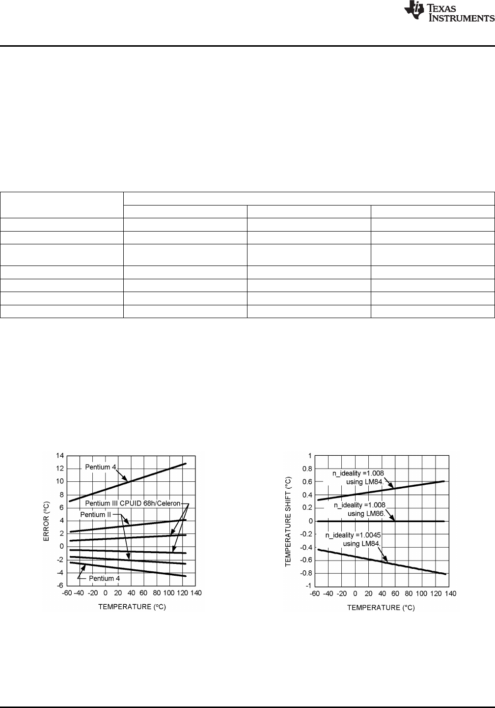
processor type has a non-ideality that strays from the typical, errors are introduced. Figure 16 shows the
minimum and maximum errors introduced to a temperature sensor calibrated specifically to the typical value of
the processor type it is connected to. The errors in this figure are attributed only to the variation in non-ideality
from the typical value. In Figure 17 is a plot of the errors that result from using a temperature sensor calibrated
for a Pentium II, the LM84, with a typical Pentium 4 or AMD Athlon MP Model 6.
Figure 16. Error Caused by Non-Ideality Factor Figure 17. Errors Induced when Temperature
Sensor is Not Calibrated to Typical Non-Ideality
22 Submit Documentation Feedback Copyright © 2004–2013, Texas Instruments Incorporated
Product Folder Links: LM90