
Datasheet


Table Of Contents
- FEATURES
- Applications
- Key Specifications
- DESCRIPTION
- Absolute Maximum Ratings
- Operating Ratings
- Temperature-to-Digital Converter Characteristics
- Logic Electrical Characteristics
- SMBus DIGITAL SWITCHING CHARACTERISTICS
- Functional Description
- CONVERSION SEQUENCE
- THE ALERT OUTPUT
- T_CRIT_A OUTPUT and T_CRIT LIMIT
- POWER ON RESET DEFAULT STATES
- SMBus INTERFACE
- TEMPERATURE DATA FORMAT
- OPEN-DRAIN OUTPUTS
- DIODE FAULT DETECTION
- COMMUNICATING with the LM90
- SERIAL INTERFACE RESET
- DIGITAL FILTER
- Fault Queue
- One-Shot Register
- LM90 REGISTERS
- COMMAND REGISTER
- LOCAL and REMOTE TEMPERATURE REGISTERS (LT, RTHB, RTLB)
- STATUS REGISTER (SR)
- CONFIGURATION REGISTER
- CONVERSION RATE REGISTER
- LOCAL and REMOTE HIGH SETPOINT REGISTERS (LHS, RHSHB, and RHSLB)
- LOCAL and REMOTE LOW SETPOINT REGISTERS (LLS, RLSHB, and RLSLB)
- REMOTE TEMPERATURE OFFSET REGISTERS (RTOHB and RTOLB)
- LOCAL and REMOTE T_CRIT REGISTERS (RCS and LCS)
- T_CRIT HYSTERESIS REGISTER (TH)
- FILTER and ALERT CONFIGURE REGISTER
- MANUFACTURERS ID REGISTER
- DIE REVISION CODE REGISTER
- Application Hints
- Revision History
LM90
SNIS126A –MAY 2004–REVISED MARCH 2013
www.ti.com
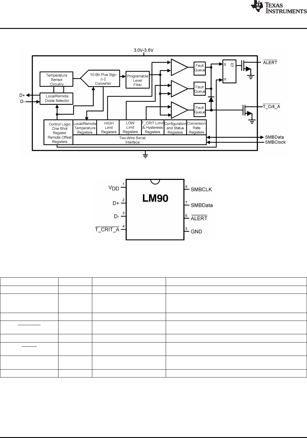
LM90 Simplified Block Diagram
Connection Diagram
Figure 1. 8-Lead VSSOP - TOP VIEW
See DGK Package
PIN DESCRIPTIONS
Label Pin # Function Typical Connection
V
DD
1 Positive Supply Voltage Input DC Voltage from 3.0 V to 3.6 V
Diode Current Source To Diode Anode. Connected to remote discrete diode conected
D+ 2 transistor junction or to the diode connected transistor junction
on a remote IC whose die temperature is being sensed.
D− 3 Diode Return Current Sink To Diode Cathode.
T_CRIT Alarm Output, Open- Pull-Up Resistor, Controller Interrupt or Power Supply
T_CRIT_A 4
Drain, Active-Low Shutdown Control
GND 5 Power Supply Ground Ground
Interrupt Output, Open-Drain, Pull-Up Resistor, Controller Interrupt or Alert Line
ALERT 6
Active-Low
SMBus Bi-Directional Data Line, From and to Controller, Pull-Up Resistor
SMBData 7
Open-Drain Output
SMBCLK 8 SMBus Input From Controller, Pull-Up Resistor
2 Submit Documentation Feedback Copyright © 2004–2013, Texas Instruments Incorporated
Product Folder Links: LM90