
Datasheet


Table Of Contents
- FEATURES
- Applications
- Key Specifications
- DESCRIPTION
- Absolute Maximum Ratings
- Operating Ratings
- Temperature-to-Digital Converter Characteristics
- Logic Electrical Characteristics
- SMBus DIGITAL SWITCHING CHARACTERISTICS
- Functional Description
- CONVERSION SEQUENCE
- THE ALERT OUTPUT
- T_CRIT_A OUTPUT and T_CRIT LIMIT
- POWER ON RESET DEFAULT STATES
- SMBus INTERFACE
- TEMPERATURE DATA FORMAT
- OPEN-DRAIN OUTPUTS
- DIODE FAULT DETECTION
- COMMUNICATING with the LM90
- SERIAL INTERFACE RESET
- DIGITAL FILTER
- Fault Queue
- One-Shot Register
- LM90 REGISTERS
- COMMAND REGISTER
- LOCAL and REMOTE TEMPERATURE REGISTERS (LT, RTHB, RTLB)
- STATUS REGISTER (SR)
- CONFIGURATION REGISTER
- CONVERSION RATE REGISTER
- LOCAL and REMOTE HIGH SETPOINT REGISTERS (LHS, RHSHB, and RHSLB)
- LOCAL and REMOTE LOW SETPOINT REGISTERS (LLS, RLSHB, and RLSLB)
- REMOTE TEMPERATURE OFFSET REGISTERS (RTOHB and RTOLB)
- LOCAL and REMOTE T_CRIT REGISTERS (RCS and LCS)
- T_CRIT HYSTERESIS REGISTER (TH)
- FILTER and ALERT CONFIGURE REGISTER
- MANUFACTURERS ID REGISTER
- DIE REVISION CODE REGISTER
- Application Hints
- Revision History
LM90
www.ti.com
SNIS126A –MAY 2004–REVISED MARCH 2013
fan started, setpoint limits adjusted, etc.
8. Master resets the ALERT mask (D7 in the Configuration register).
The ARA, 000 1100, is a general call address. No device should ever be assigned this address.
Bit D0 (the ALERT configure bit) in the FILTER and ALERT CONFIGURE REGISTER (xBF) must be set low in
order for the LM90 to respond to the ARA command.
The ALERT output can be disabled by setting the ALERT mask bit, D7, of the Configuration register. The power
on default is to have the ALERT mask bit and the ALERT configure bit low.
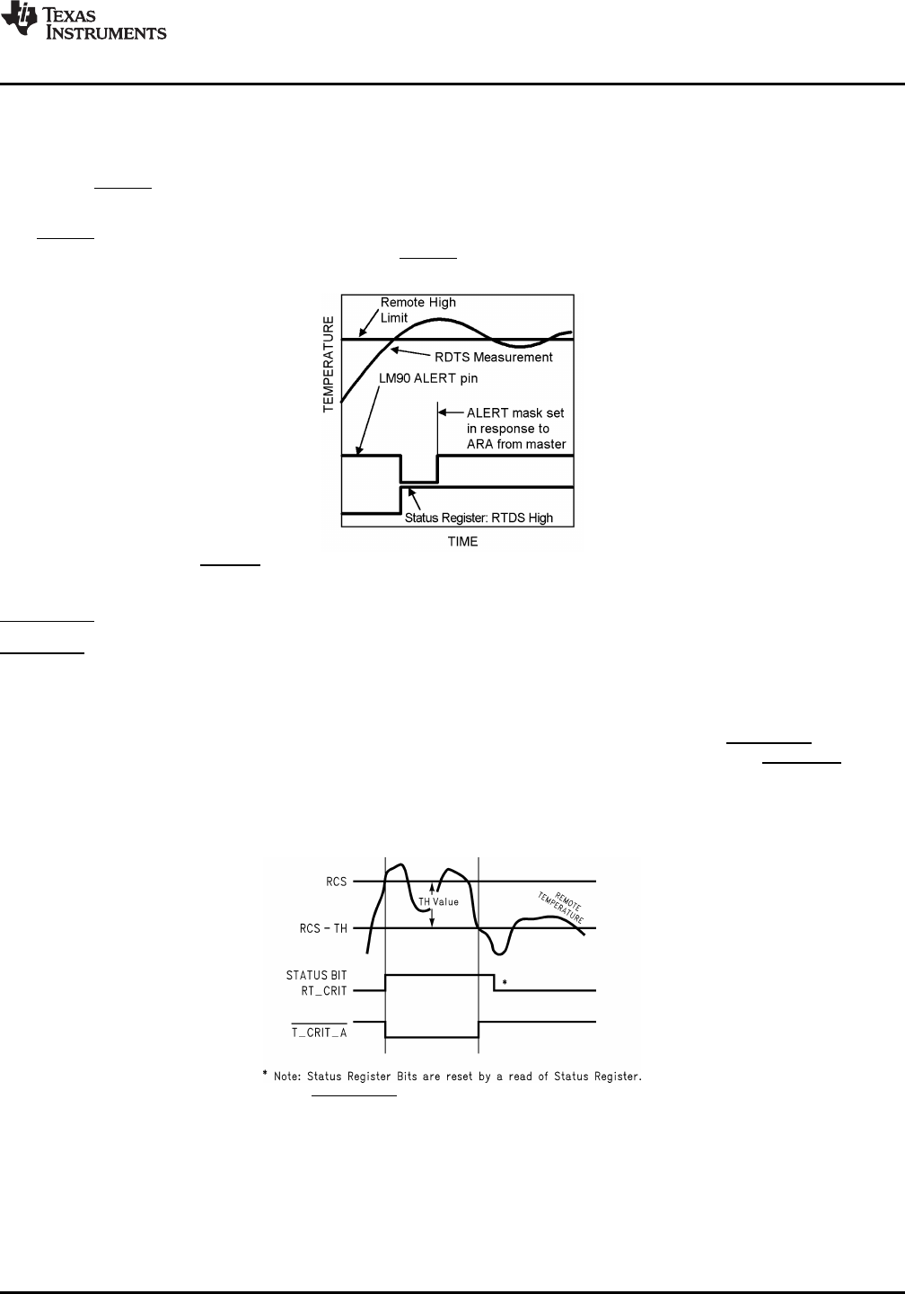
Figure 6. ALERT Output as an SMBus ALERT Temperature Response Diagram
T_CRIT_A OUTPUT and T_CRIT LIMIT
T_CRIT_A is activated when any temperature reading is greater than the limit preset in the critical temperature
setpoint register (T_CRIT), as shown in Figure 7. The Status Register can be read to determine which event
caused the alarm. A bit in the Status Register is set high to indicate which temperature reading exceeded the
T_CRIT setpoint temperature and caused the alarm, see STATUS REGISTER (SR).
Local and remote temperature diodes are sampled in sequence by the A/D converter. The T_CRIT_A output and
the Status Register flags are updated after every Local and Remote temperature conversion. T_CRT_A follows
the state of the comparison, it is reset when the temperature falls below the setpoint RCS-TH. The Status
Register flags are reset only after the Status Register is read and if a temperature conversion(s) is/are below the
T_CRIT setpoint, as shown in Figure 7
Figure 7. T_CRIT_A Temperature Response Diagram
POWER ON RESET DEFAULT STATES
LM90 always powers up to these known default states. The LM90 remains in these states until after the first
conversion.
1. Command Register set to 00h
2. Local Temperature set to 0°C
Copyright © 2004–2013, Texas Instruments Incorporated Submit Documentation Feedback 11
Product Folder Links: LM90