
Datasheet


Table Of Contents
- FEATURES
- Applications
- Key Specifications
- DESCRIPTION
- Absolute Maximum Ratings
- Operating Ratings
- Temperature-to-Digital Converter Characteristics
- Logic Electrical Characteristics
- SMBus DIGITAL SWITCHING CHARACTERISTICS
- Functional Description
- CONVERSION SEQUENCE
- THE ALERT OUTPUT
- T_CRIT_A OUTPUT and T_CRIT LIMIT
- POWER ON RESET DEFAULT STATES
- SMBus INTERFACE
- TEMPERATURE DATA FORMAT
- OPEN-DRAIN OUTPUTS
- DIODE FAULT DETECTION
- COMMUNICATING with the LM90
- SERIAL INTERFACE RESET
- DIGITAL FILTER
- Fault Queue
- One-Shot Register
- LM90 REGISTERS
- COMMAND REGISTER
- LOCAL and REMOTE TEMPERATURE REGISTERS (LT, RTHB, RTLB)
- STATUS REGISTER (SR)
- CONFIGURATION REGISTER
- CONVERSION RATE REGISTER
- LOCAL and REMOTE HIGH SETPOINT REGISTERS (LHS, RHSHB, and RHSLB)
- LOCAL and REMOTE LOW SETPOINT REGISTERS (LLS, RLSHB, and RLSLB)
- REMOTE TEMPERATURE OFFSET REGISTERS (RTOHB and RTOLB)
- LOCAL and REMOTE T_CRIT REGISTERS (RCS and LCS)
- T_CRIT HYSTERESIS REGISTER (TH)
- FILTER and ALERT CONFIGURE REGISTER
- MANUFACTURERS ID REGISTER
- DIE REVISION CODE REGISTER
- Application Hints
- Revision History
LM90
SNIS126A –MAY 2004–REVISED MARCH 2013
www.ti.com
Configuration register).
4. Master attends to conditions that caused the ALERT to be triggered. The fan is started, setpoint limits are
adjusted, etc.
5. Master resets the ALERT mask (D7 in the Configuration register).
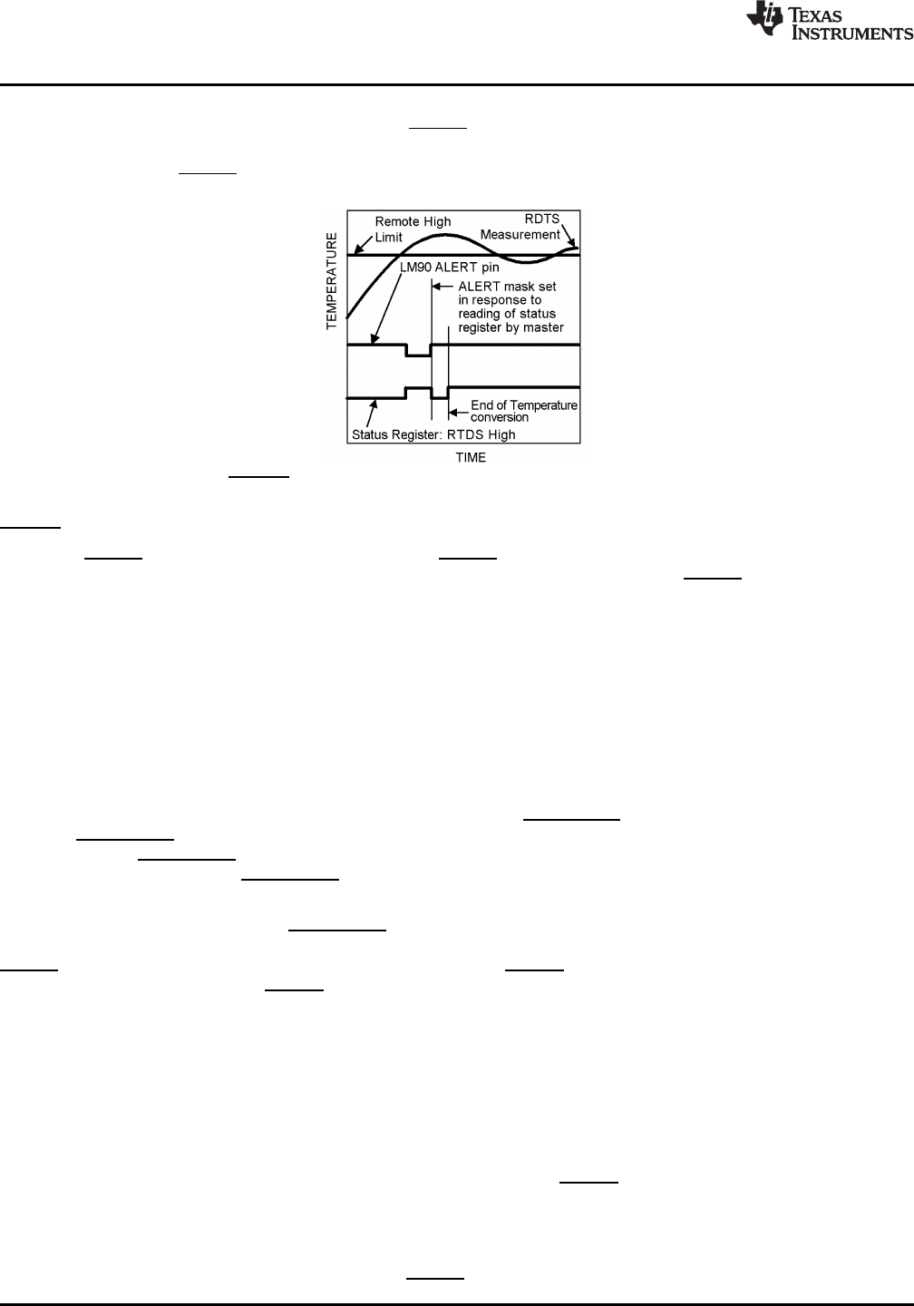
Figure 5. ALERT Output as an Interrupt Temperature Response Diagram
ALERT Output as an SMBus ALERT
When the ALERT output is connected to one or more ALERT outputs of other SMBus compatible devices and to
a master, an SMBus alert line is created. Under this implementation, the LM90's ALERT should be operated
using the ARA (Alert Response Address) protocol. The SMBus 2.0 ARA protocol, defined in the SMBus
specification 2.0, is a procedure designed to assist the master in resolving which part generated an interrupt and
service that interrupt while impeding system operation as little as possible.
The SMBus alert line is connected to the open-drain ports of all devices on the bus thereby AND'ing them
together. The ARA is a method by which with one command the SMBus master may identify which part is pulling
the SMBus alert line LOW and prevent it from pulling it LOW again for the same triggering condition. When an
ARA command is received by all devices on the bus, the devices pulling the SMBus alert line LOW, first, send
their address to the master and second, release the SMBus alert line after recognizing a successful transmission
of their address.
The SMBus 1.1 and 2.0 specification state that in response to an ARA (Alert Response Address) “after
acknowledging the slave address the device must disengage its SMBALERT pulldown”. Furthermore, “if the host
still sees SMBALERT low when the message transfer is complete, it knows to read the ARA again”. This SMBus
“disengaging of SMBALERT” requirement prevents locking up the SMBus alert line. Competitive parts may
address this “disengaging of SMBALERT” requirement differently than the LM90 or not at all. SMBus systems
that implement the ARA protocol as suggested for the LM90 will be fully compatible with all competitive parts.
The LM90 fulfills “disengaging of SMBALERT” by setting the ALERT mask bit (bit D7 in the Configuration
register, at address 09h) after successfully sending out its address in response to an ARA and releasing the
ALERT output pin. Once the ALERT mask bit is activated, the ALERT output pin will be disabled until enabled by
software. In order to enable the ALERT the master must read the STATUS REGISTER, at address 02h, during
the interrupt service routine and then reset the ALERT mask bit in the Configuration register to 0 at the end of
the interrupt service routine.
The following sequence describes the ARA response protocol.
1. Master Senses SMBus alert line low
2. Master sends a START followed by the Alert Response Address (ARA) with a Read Command.
3. Alerting Device(s) send ACK.
4. Alerting Device(s) send their Address. While transmitting their address, alerting devices sense whether their
address has been transmitted correctly. (The LM90 will reset its ALERT output and set the ALERT mask bit
once its complete address has been transmitted successfully.)
5. Master/slave NoACK
6. Master sends STOP
7. Master attends to conditions that caused the ALERT to be triggered. The STATUS REGISTER is read and
10 Submit Documentation Feedback Copyright © 2004–2013, Texas Instruments Incorporated
Product Folder Links: LM90