
Datasheet


Table Of Contents
- Features
- Applications
- Key Specifications
- Description
- Absolute Maximum Ratings
- Operating Ratings
- Temperature-to-Digital Converter Characteristics
- Logic Electrical Characteristics
- DIGITAL DC CHARACTERISTICS
- SMBus DIGITAL SWITCHING CHARACTERISTICS
- Functional Description
- LM86 REGISTERS
- COMMAND REGISTER
- LOCAL and REMOTE TEMPERATURE REGISTERS (LT, RTHB, RTLB)
- STATUS REGISTER (SR)
- CONFIGURATION REGISTER
- CONVERSION RATE REGISTER
- LOCAL and REMOTE HIGH SETPOINT REGISTERS (LHS, RHSHB, and RHSLB)
- LOCAL and REMOTE LOW SETPOINT REGISTERS (LLS, RLSHB, and RLSLB)
- REMOTE TEMPERATURE OFFSET REGISTERS (RTOHB and RTOLB)
- LOCAL and REMOTE T_CRIT REGISTERS (RCS and LCS)
- T_CRIT HYSTERESIS REGISTER (TH)
- FILTER and ALERT CONFIGURE REGISTER
- MANUFACTURERS ID REGISTER
- DIE REVISION CODE REGISTER
- APPLICATION HINTS
- Data Sheet Revision History
LM86
SNIS114E –DECEMBER 2001–REVISED MARCH 2013
www.ti.com
For RTLB D7–D5: Temperature Data. LSB = 0.125°C. Two's complement format.
The maximum value available from the Local Temperature register is 127; the minimum value available from the
Local Temperature register is -128. The maximum value available from the Remote Temperature register is
127.875; the minimum value available from the Remote Temperature registers is −128.875.
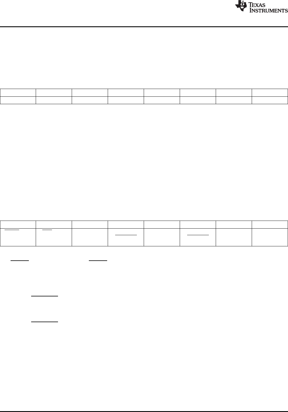
STATUS REGISTER (SR)
Table 4. STATUS REGISTER (SR) (Read Only Address 02h):
D7 D6 D5 D4 D3 D2 D1 D0
Busy LHIGH LLOW RHIGH RLOW OPEN RCRIT LCRIT
Power up default is with all bits “0” (zero).
D0: LCRIT: When set to “1” indicates a Local Critical Temperature alarm.
D1: RCRIT: When set to “1” indicates a Remote Diode Critical Temperature alarm.
D2: OPEN: When set to “1” indicates a Remote Diode disconnect.
D3: RLOW: When set to “1” indicates a Remote Diode LOW Temperature alarm
D4: RHIGH: When set to “1” indicates a Remote Diode HIGH Temperature alarm.
D5: LLOW: When set to “1” indicates a Local LOW Temperature alarm.
D6: LHIGH: When set to “1” indicates a Local HIGH Temperature alarm.
D7: Busy: When set to “1” ADC is busy converting.
CONFIGURATION REGISTER
Table 5. CONFIGURATION REGISTER (Read Address 03h /Write Address 09h):
D7 D6 D5 D4 D3 D2 D1 D0
ALERT mask RUN/STOP 0 Remote 0 Local 0 Fault Queue
T_CRIT_A T_CRIT_A
mask mask
Power up default is with all bits “0” (zero)
D7: ALERT mask: When set to “1” ALERT interrupts are masked.
D6: RUN/STOP: When set to “1” SHUTDOWN is enabled.
D5: is not defined and defaults to “0”.
D4: Remote T_CRIT mask: When set to “1” a diode temperature reading that exceeds T_CRIT setpoint will not
activate the T_CRIT_A pin.
D3: is not defined and defaults to “0”.
D2: Local T_CRIT mask: When set to “1” a Local temperature reading that exceeds T_CRIT setpoint will not
activate the T_CRIT_A pin.
D1: is not defined and defaults to “0”.
D0: Fault Queue: when set to “1” three consecutive remote temperature measurements outside the HIGH, LOW,
or T_CRIT setpoints will trigger an “Outside Limit” condition resulting in setting of status bits and associated
output pins..
18 Submit Documentation Feedback Copyright © 2001–2013, Texas Instruments Incorporated
Product Folder Links: LM86