
Datasheet


LM81
www.ti.com
SNAS011E –JUNE 1999–REVISED FEBRUARY 2002
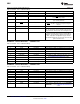
Power on default - <7:0> = 0100 0100 binary
Bit Name Read/Write Description
1 LOW Limit Mask Bit Read/Write A mask bit for the LOW limit Interrupt. A one disables the
interrupt from propagating to the INT pin.
2-3 T_CRIT_A Interrupt Read/Write The state of these bits select the interrupt mode for
Mode Select T_CRIT_A as described below.
<3:2> = 00 or <3:2> = 11: Repetitive Interrupt Mode
<3:2> = 01: One-Time Interrupt Mode
<3:2> = 10: Comparator Mode
4 T_CRIT_A Enable Read/Write A one enables the T_CRIT_A pin.
5 T_CRIT_A Polarity Read/Write A one sets the T_CRIT_A pin active HIGH. A zero sets
the T_CRIT_A pin active LOW.
6 T_CRIT_A Mask Read/Write A one prevents the T_CRIT_A interrupt from propagating
Enable to the INT output pin.
7 T_CRIT_A Status Bit Read A one indicates that a T_CRIT_A interrupt has occurred.
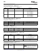
EXTENDED MODE REGISTER 2 — ADDRESS 4DH
Power on default - <7:0> = 0000 0000 binary
Bit Name Read/Write Description
0-2 Hysteresis Offset Read/Write T
HYST
value.
Value
3 12-bit Temperature Read/Write A one sets the temperature resolution to 12 bits.
Resolution Enable
4-7 12-bit Temperature Read Only 12-bit temperature data least significant bits. Bit 7
Data mirrors bit 7 in the temperature configuration register
(4Bh) and has a weight of 0.5˚C; bits 6-4 have a weight
of 0.25, 0.125, and 0.0625˚C, respectively.
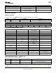
VALUE RAM — ADDRESS 15H–3FH
Address A6–A0
(1)
Description
(1)
15h Manufacturers Test Register
19h DAC data register; power on default <7:0> =1111 1111 binary
20h +2.5Vin reading
21h Vccp1 reading
22h +3.3Vin reading
23h +5Vin reading
24h +12Vin reading
25h Vccp2 reading
26h Reserved reading
27h Temperature reading (8 MSBs)
28h FAN1 reading
(2)
29h FAN2 reading
(2)
2Ah Reserved
2Bh +2.5Vin High Limit
2Ch +2.5Vin Low Limit
2Dh Vccp1 High Limit
2Eh Vccp1 Low Limit
2Fh +3.3Vin High Limit
30h +3.3Vin Low Limit
(1) Setting all ones to the high limits for voltages and fans (0111 1111 binary for temperature) means interrupts will never be generated
except the case when voltages go below the low limits. For voltage input high limits, the device is doing a greater than comparison. For
low limits, however, it is doing a less than or equal to comparison.
(2) This location stores the number of counts of the internal clock per revolution.
Copyright © 1999–2002, Texas Instruments Incorporated Submit Documentation Feedback 35
Product Folder Links: LM81