
Datasheet

LM81
www.ti.com
SNAS011E –JUNE 1999–REVISED FEBRUARY 2002
External Interrupts can come from the following source. While the label suggests a specific type or source of
Interrupt, this label is not a restriction of its usage, and it could come from any desired source:
• Chassis Intrusion: This is an active high interrupt from any type of device that detects and captures chassis
intrusion violations. This could be accomplished mechanically, optically, or electrically, and circuitry external
to the LM81 is expected to latch the event. The design of the LM81 allows this input to go high even with no
power applied to the LM81, and no clamping or other interference with the line will occur. This line can also
be pulled low for at least 20 ms by the LM81 to reset a typical Chassis Intrusion circuit. Accomplish this reset
by setting Bit 7 of CI Clear Register (45h) high. The bit in the Register is self-clearing.
All interrupts are indicated in the two Interrupt Status Registers. The INT output has two mask registers, and
individual masks for each Interrupt. As described in the USING THE CONFIGURATION REGISTER section, the
hardware Interrupt line can also be enabled/disabled in the Configuration Register.
T_CRIT_A interrupt is dedicated to temperature and is indicated in Extended Mode Register 1. Extended Mode
Register 1 controls T_CRIT_A.
INTERRUPT CLEARING
Reading a Status Register will output the contents of the Register, and reset the Register. A subsequent read
done before the analog “round-robin” monitoring loop is complete will indicate a cleared Register. Allow at least
820 ms to allow all Registers to be updated between reads. In summary, the Interrupt Status Register clears
upon being read, and requires at least 400 ms to be updated. When the Interrupt Status Register clears, the
hardware interrupt line will also clear until the Registers are updated by the monitoring loop. The hardware
Interrupt line (INT) is cleared with the INT_Clear bit, which is Bit 3 of the Configuration Register. When this bit is
high, the LM81 monitoring loop will stop. It will resume when the bit is low.
RESET I/O
RESET is intended to provide a master reset to devices connected to this line. INT Mask Register 2, Bit 7, must
be set high to enable this function. Setting Bit 4 in the Configuration Register high outputs a least 20 ms low on
this line, at the end of which Bit 4 in the Configuration Register automatically clears. Again, the label for this pin
is only its suggested use. In applications where the RESET capability is not needed it can be used for any type
of digital control that requires a 20 ms active low open-drain output.
RESET operates as an input when not activated by the Configuration Register. Setting this line low will reset all
of the registers in the LM81 to their power on default state. All Value RAM locations will not be affected except
for the DAC Data Register.
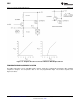
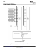
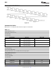
NAND TREE TESTS
A NAND tree is provided in the LM81 for Automated Test Equipment (ATE) board level connectivity testing.
DACOut/ NTEST_IN, T_CRIT_A, V+ and GND pins are excluded from NAND tree testing. Taking
DACOut/NTEST_IN high before the first write to the configuration register activates the NAND Tree test mode.
After the first write to the configuration register the NAND Tree test mode cannot be reactivated. To perform a
NAND tree test all pins included in the NAND tree should be driven to 1 forcing the A0/ NTEST_OUT high. Each
individual pin starting with A1 and concluding with SMBData (excluding DACOut/NTEST_IN, T_CRIT_A, V+ and
GND) can be taken low with the resulting toggle observed on the A0/NTEST_OUT pin. Allow for a typical
propagation delay of 500 ns.
Copyright © 1999–2002, Texas Instruments Incorporated Submit Documentation Feedback 29
Product Folder Links: LM81