
Datasheet

LM81
www.ti.com
SNAS011E –JUNE 1999–REVISED FEBRUARY 2002
DAC OUTPUT
The LM81 provides an 8-bit DAC (Digital-to-Analog Converter) with an output range of 0 to 1.25 volts (4.88 mV
LSB). This DAC can be used in any way, but in most applications of the LM81 the DAC will be used for fan
control. Typically the DAC output would be amplified to provide the up to 12 volt drive required by the fan. At
power-on the DAC provides full output, insuring that full fan speed is the default condition. Care should be taken
such that the analog circuitry tied to this pin does not drive this pin above 2.5V. Doing so will place the LM81 in
NAND tree test mode which will make all pins inputs, thus disabling any response from the LM81.
Fans do not start reliably at reduced voltages, so operation at a reduced voltage should be preceded by a brief
(typically 1 second) excursion to full operating voltage, then reduce the voltage. Most fans do not operate at all
below 5 to 7 volts. At those lower voltages the fan will simply consume current, dissipate power, and not operate
and such conditions should be avoided.
The output of the amplifier can be configured to provide a high or low side pass transistor. A high side pass
transistor simplifies the coupling of tachometer outputs to the tachometer inputs of the LM81 since the fan
remains grounded. Low side drive will require AC coupling along with clamping at the LM81 input to prevent
negative excursions.
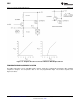
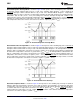
A typical circuit for fan drive is shown in Figure 16. R4 is used when a negative power supply is available to
eliminate offset in the amplifier and provide a 0 to 11.5 volt output (actually 12 volts less saturation). Omitting R4
will create a “dead zone” between approximately 0 to 6 volts output (a potentially unusable region anyway). In
many applications protecting the pass transistor Q2 from faults such as a shorted fan can be accomplished by
taking advantage of the current limit already existing on the 12 volt supply. Q2 will have to be heat-sunk
accordingly. Otherwise, use the suggested current limit circuit as shown.
Copyright © 1999–2002, Texas Instruments Incorporated Submit Documentation Feedback 21
Product Folder Links: LM81