
Datasheet

6
1.35 10
Count
RPM Divisor
u
u
LM81
www.ti.com
SNAS011E –JUNE 1999–REVISED FEBRUARY 2002
ANALOG INPUT INTERRUPTS
A WATCHDOG window comparison on the analog inputs can activate the INT interrupt output. A converted input
voltage that is above its respective HIGH limit or less than or equal to its LOW limit will cause a flag to be set in
its Interrupt Status Register. This flag will activate the INT output when its mask bit is set low. Mask bits are
found in the Interrupt Mask Registers.
LAYOUT AND GROUNDING
A separate, low-impedance ground plane for analog ground, which provides a ground point for both GND pins,
voltage dividers and other analog components, will provide best performance but is not mandatory. Analog
components such as voltage dividers should be located physically as close as possible to the LM81.
The power supply bypass, the parallel combination of 10 μF (electrolytic or tantalum) and 0.1 μF (ceramic)
bypass capacitors connected between pin 12 and ground, should also be located as close as possible to the
LM81.
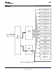
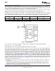
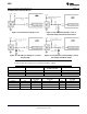
FAN INPUTS
The FAN1 and FAN2 inputs accept signals from fans equipped with tachometer outputs. These are logic-level
inputs with an approximate threshold of V+/2. Signal conditioning in the LM81 accommodates the slow rise and
fall times typical of fan tachometer outputs. The maximum input signal range is 0 to V+. In the event these inputs
are supplied from fan outputs which exceed 0 to V+, either resistive division or diode clamping must be included
to keep inputs within an acceptable range, as shown in the ALTERNATIVES FOR FAN INPUTS section. R2 is
selected so that it does not develop excessive voltage due to input leakage. R1 is selected based on R2 to
provide a minimum input of 2V and a maximum of V+. R1 should be as low as possible to provide the maximum
possible input up to V+ for best noise immunity. Alternatively, use a shunt reference or zener diode to clamp the
input level.
If fans can be powered while the power to the LM81 is off, the LM81 inputs will provide diode clamping. Limit
input current to the Input Current at Any Pin specification shown in the ABSOLUTE MAXIMUM RATINGS
(5)(6)(7)
section. In most cases, open collector outputs with pull-up resistors inherently limit this current. If this maximum
current could be exceeded, either a larger pull up resistor should be used or resistors connected in series with
the fan inputs.
The Fan Inputs gate an internal 22.5 kHz oscillator for one period of the Fan signal into an 8-bit counter
(maximum count = 255). The default divisor, located in the VID/Fan Divisor Register, is set to 2 (choices are 1, 2,
4, and 8) providing a nominal count of 153 for a 4400 rpm fan with two pulses per revolution. Typical practice is
to consider 70% of normal RPM a fan failure, at which point the count will be 219.
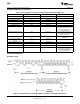
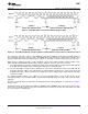
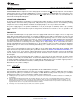
Determine the fan count according to:
(2)
Note that Fan 1 and Fan 2 Divisors are programmable via the VID/Fan Divisor Register.
Fan tachometer outputs that provide one pulse per revolution should use a divisor setting twice that of outputs
that provide two pulses per revolution. For example, a 4400 RPM fan that provides one pulse per revolution
should have the divisor set to 4 such that the nominal counter output is 153.
(5) If Military/Aerospace specified devices are required, please contact the Texas Instruments Sales Office/ Distributors for availability and
specifications.
(6) Absolute Maximum Ratings indicate limits beyond which damage to the device may occur. Operating Ratings indicate conditions for
which the device is functional, but do not ensure specific performance limits. For ensured specifications and test conditions, see the
Electrical Characteristics. The ensured specifications apply only for the test conditions listed. Some performance characteristics may
degrade when the device is not operated under the listed test conditions.
(7) All voltages are measured with respect to GND, unless otherwise specified.
Copyright © 1999–2002, Texas Instruments Incorporated Submit Documentation Feedback 19
Product Folder Links: LM81