
Datasheet

LM81
SNAS011E –JUNE 1999–REVISED FEBRUARY 2002
www.ti.com
USING THE LM81
POWER ON
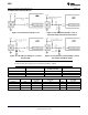
When power is first applied, the LM81 performs a “power on reset” on several of its registers. The power on
condition of the LM81’s registers in shown in Table 1 Registers whose power on values are not shown have
power on conditions that are indeterminate (this includes the value RAM ,exclusive of the DAC data, and
WATCHDOG limits). When power is first applied the ADC is inactive. In most applications, usually the first action
after power on is usually to write WATCHDOG limits into the Value RAM. Register values can be returned to
their default values after power is applied to the LM81 by taking RESET low for at least 50 ns.
RESETS
Configuration Register INITIALIZATION accomplishes the same function as power on reset on most registers.
The Value RAM conversion results, and Value RAM WATCHDOG limits are not Reset and will be indeterminate
immediately after power on. If the Value RAM contains valid conversion results and/or Value RAM WATCHDOG
limits have been previously set, they will not be affected by a Configuration Register INITIALIZATION. Power on
reset, or Configuration Register INITIALIZATION, clear or initialize the following registers (the initialized values
are shown in Table 3:
• Configuration Register
• Interrupt Status Register 1
• Interrupt Status Register 2
• INT Mask Register 1
• INT Mask Register 2
• VID/Fan Divisor Register
• Serial Bus Address Register (Power on reset only, not reset by Configuration Register INITIALIZATION)
• VID4 Register
• Temperature Configuration Register
• Extended Mode Register 1
• Extended Mode Register 2
Configuration Register INITIALIZATION is accomplished by setting Bit 7 of the Configuration Register high. This
bit automatically clears after being set.
USING THE CONFIGURATION REGISTER
The Configuration Register controls the LM81 operation. At power on, the ADC is stopped and INT_Clear is
asserted, clearing the INT hardwire output. The Configuration Register starts and stops the LM81, enables and
disables interrupt output, and provides the Reset function described in the RESETS section.
Bit 0 of the Configuration Register controls the monitoring loop of the LM81. Setting Bit 0 low stops the LM81
monitoring loop and puts the LM81 in shutdown mode, reducing power consumption. Serial Bus communication
can take place with any register in the LM81 although activity on the SMBData and SMBCLK lines will increase
shutdown current, up to as much as maximum rated supply current, while the activity takes place. Taking Bit 0
high starts the monitoring loop, described in more detail subsequently.
Bit 1 of the Configuration Register enables the INT Interrupt hardwire output when this bit is taken high.
Bit 3 of the Configuration Register clears the INT output when set high, without affecting the contents of the
Interrupt Status Registers. The LM81 will stop monitoring. It will resume upon clearing of this bit.
Bit 4 of the Configuration Register provides an active low 20 ms pulse at the RESET output when set high.
The CI_Clear provides an active low 20 ms pulse at the CI output pin when set high. This is intended for
resetting the Chassis Intrusion circuitry.
The INITIALIZATION bit resets the internal registers of the LM81 as described in the RESETS section.
16 Submit Documentation Feedback Copyright © 1999–2002, Texas Instruments Incorporated
Product Folder Links: LM81