
Datasheet

LM81
SNAS011E –JUNE 1999–REVISED FEBRUARY 2002
www.ti.com
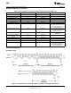
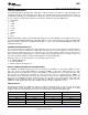
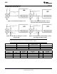
INTERNAL REGISTERS OF THE LM81
Table 3. Internal Registers and Their Corresponding Internal LM81 Addresses
Register LM81 Internal Hex Address Power On Value Notes
Configuration Register 40h 0000 1000
Interrupt Status Register 1 41h 0000 0000
Interrupt Status Register 2 42h 0000 0000
Interrupt Mask Register 1 43h 0000 0000
Interrupt Mask Register 2 44h 0000 0000
CI Clear Register 46h 0000 0000
VID/Fan Divisor Register 47h 0101 XXXX The upper four bits set the divisor
for Fan Counters 1 and 2. The
lower four bits reflect the state of
the VID0-VID3 inputs.
Serial Bus Address Register 48h 0010 11XX The lower 2 bits reflect the state
of A1 and A0, the Serial Bus
address input pins.
VID4 Register 49h 1000 000X The lower bit reflects the state of
VID4 input.
Temperature Configuration 4Bh 0000 0001
Register
Extended Mode Register 1 4Ch 0100 0100
Extended Mode Register 2 4Dh 0000 0000
Value RAM DAC Data Register 19h 1111 1111
Value RAM 20h-3Fh Contains: monitoring results
(temperature, voltages, fan
counts), WATCHDOG limits, and
Company/Stepping IDs
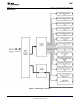
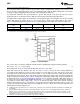
SERIAL BUS INTERFACE
Serial Bus Timing
Figure 8. Serial Bus Write to the Internal Address Register followed by the Data Byte
14 Submit Documentation Feedback Copyright © 1999–2002, Texas Instruments Incorporated
Product Folder Links: LM81