
Datasheet

LM81
SNAS011E –JUNE 1999–REVISED FEBRUARY 2002
www.ti.com
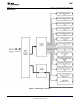
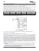
The LM81 has several internal registers, as shown in Figure 7, Table 3 and the REGISTERS AND RAM section.
These include:
• Configuration Register: Provides control and configuration.
• Interrupt Status Registers: Two registers to provide status of each WATCHDOG limit or Interrupt event.
• Interrupt Mask Registers: Allows masking of individual Interrupt sources, as well as separate masking for
each of the two hardware Interrupt outputs.
• CI Clear Register: Allows transmitting a 20 ms low pulse on the chassis intrusion pin (CI).
• VID/Fan Divisor Register: This register contains the state of the VID0-VID3 input lines and the divisor bits
for FAN1 and FAN2 inputs.
• Serial Bus Address Register: Contains the Serial Bus address. At power on it assumes the default value of
01011XX binary, and can be altered by the state of A0 and A1.
• VID4 Register: Contains the state of the VID4 input.
• Temperature Configuration Register: Selects the interrupt mode and contains the 0.5˚C LSB of the
temperature reading.
• Extended Mode Registers: Enable and control the Extended Mode which includes the LSBs of the 12-bit
temperature reading, T_CRIT, and T
HYST
• Value RAM: The DAC digital input, monitoring results (temperature, voltages, fan counts), WATCHDOG
limits, and Company/Stepping IDs are all contained in the Value RAM. The Value RAM consists of a total of
34 bytes, addresses 15h - 3Fh, containing:
– byte 1 at address 15h a manufacturers test register
– locations 16h - 18h are unassigned and do not have associated registers
– byte 2 at address 19h contains the DAC Data Register
– locations 1Ah - 1Fh are unassigned and do not have associated registers
– the next 10 bytes at addresses 20h -29h contain all of the results, with address 26h reserved
– the next 18 bytes at addresses 2Bh-3Ch are the WATCHDOG limits
– the last 2 bytes at addresses 3Eh and 3Fh contain the Company ID and Stepping ID numbers,
respectively
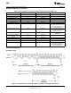
When the LM81 is started, it cycles through each measurement in sequence, and it continuously loops through
the sequence approximately once every 400 ms. Each measured value is compared to values stored in
WATCHDOG, or Limit registers. When the measured value violates the programmed limit the LM81 will set a
corresponding Interrupt in the Interrupt Status Registers. The hardware Interrupt line INT is fully programmable
with separate masking of each Interrupt source. In addition, the Configuration Register has a control bit to enable
or disable the hardware Interrupt.
Another hardware Interrupt line available T_CRIT_A (Critical Temperature Alarm Output) is used to signal a
catastrophic overtemperature event. Having a dedicated interrupt for this purpose allows for the fastest possible
response time to a thermal runaway event. This output can be enabled by setting bit 4 of Extended Mode
Register 1.
The Chassis Intrusion input is designed to accept an active high signal from an external circuit that latches when
the case is removed from the computer.
12 Submit Documentation Feedback Copyright © 1999–2002, Texas Instruments Incorporated
Product Folder Links: LM81