
Datasheet

LM81
www.ti.com
SNAS011E –JUNE 1999–REVISED FEBRUARY 2002
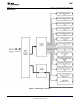
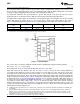
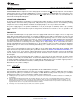
TEST CIRCUIT
Figure 6. Digital Output Load Test Circuitry
FUNCTIONAL DESCRIPTION
GENERAL DESCRIPTION
The LM81 provides 6 analog inputs, a temperature sensor, a Delta-Sigma ADC (Analog-to-Digital Converter), a
DAC output, 2 fan speed counters, WATCHDOG registers, and a variety of inputs and outputs on a single chip. A
two wire Serial Bus interface is included. The LM81 performs power supply, temperature, fan control and fan
monitoring for personal computers.
The analog inputs are useful for monitoring several power supplies present in a typical computer. The LM81
includes internal resistor dividers that scale and/or offset external Vccp, +2.5V, +3.3V, +5.0V and +12V power
supply voltages to a 3/4 scale nominal ADC output. The LM81 ADC then continuously converts the scaled inputs
to 8-bit digital words. Measurement of negative voltages (such as -5V and -12V power supplies) can be
accommodated with an external resistor divider applied to the Vccp2 input. Temperature is converted to a 9-bit or
12-bit two’s-complement digital word with a 0.5˚C LSB or 0.0625˚C LSB, respectively.
Fan inputs measure the period of tachometer pulses from the fans, providing a higher count for lower fan
speeds. The fan inputs are Schmitt-Trigger digital inputs with an acceptable range of 0V to V+ and a transition
level of approximately V+/2. Full scale fan counts are 255 (8-bit counter) and this represents a stopped or very
slow fan. Nominal speeds, based on a count of 153, are programmable from 1100 to 8800 RPM on FAN1 and
FAN2. Schmitt-Trigger input circuitry is included to accommodate slow rise and fall times. A 0V to 1.25V DAC
output voltage range can be used for control of fan speed.
Copyright © 1999–2002, Texas Instruments Incorporated Submit Documentation Feedback 11
Product Folder Links: LM81