
Datasheet


LM75B, LM75C
SNIS153B –JULY 2009–REVISED MARCH 2013
www.ti.com
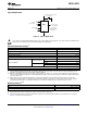
Thermal
Package
Device Number Resistance
Number
(θ
JA
)
LM75BIM-3, LM75BIM-5,
D (R-PDSO-G8) 200°C/W
LM75CIM-3, LM75CIM-5
LM75BIMM-3, LM75BIMM-5, DGK (S-PDSO-
250°C/W
LM75CIMM-3, LM75CIMM-5 G8)
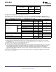
Temperature-to-Digital Converter Characteristics
(1)
Unless otherwise noted, these specifications apply for: +V
S
= +5 Vdc for LM75BIM-5, LM75BIMM-5, LM75CIM-5, and
LM75CIMM-5; and +V
S
= +3.3 Vdc for LM75BIM-3, LM75BIMM-3, LM75CIM-3, and LM75CIMM-3
(2)
. Boldface limits apply
for T
A
= T
J
= T
MIN
to T
MAX
; all other limits T
A
= T
J
= +25°C, unless otherwise noted.
Parameter Conditions Typical
(3)
Limits
(4)
Units (Limit)
T
A
= −25°C to +100°C ±2.0
Accuracy °C (max)
T
A
= −55°C to +125°C ±3.0
Resolution 9 Bits
Temperature Conversion Time See
(5)
100 300 ms (max)
I
2
C Inactive 0.25 0.5 mA (max)
LM75B Shutdown Mode, +V
S
= 3V 4
μA
Shutdown Mode, +V
S
= 5V 6
Quiescent Current
I
2
C Inactive 0.25 1.0 mA (max)
LM75C Shutdown Mode, +V
S
= 3V 4
μA
Shutdown Mode, +V
S
= 5V 6
O.S. Output Saturation Voltage I
OUT
= 4.0 mA 0.8 V (max)
(6)
1 Conversion (min)
O.S. Delay
6 Conversions (max)
T
OS
Default Temperature 80
See
(7)
°C
T
HYST
Default Temperature 75
(1) For best accuracy, minimize output loading. Higher sink currents can affect sensor accuracy with internal heating. This can cause an
error of 0.64°C at full rated sink current and saturation voltage based on junction-to-ambient thermal resistance.
(2) All part numbers of the LM75 will operate properly over the +V
S
supply voltage range of 3V to 5.5V. The devices are tested and
specified for rated accuracy at their nominal supply voltage. Accuracy will typically degrade 1°C/V of variation in +V
S
as it varies from
the nominal value.
(3) Typicals are at T
A
= 25°C and represent most likely parametric norm.
(4) Limits are specified to AOQL (Average Outgoing Quality Level).
(5) The conversion-time specification is provided to indicate how often the temperature data is updated. The LM75 can be accessed at any
time and reading the Temperature Register will yield result from the last temperature conversion. When the LM75 is accessed, the
conversion that is in process will be interrupted and it will be restarted after the end of the communication. Accessing the LM75
continuously without waiting at least one conversion time between communications will prevent the device from updating the
Temperature Register with a new temperature conversion result. Consequently, the LM75 should not be accessed continuously with a
wait time of less than 300 ms.
(6) O.S. Delay is user programmable up to 6 “over limit” conversions before O.S. is set to minimize false tripping in noisy environments.
(7) Default values set at power up.
4 Submit Documentation Feedback Copyright © 2009–2013, Texas Instruments Incorporated
Product Folder Links: LM75B LM75C