
Datasheet


7
6
5
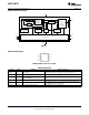
A0
A1
A2
Temperature
Threshold
Silicon Bandgap
Temperature
Sensor
Ð
1-Bit
D/A
10-Bit
Digital
Decimation
Filter
9-Bit Sigma-Delta ADC
Configuration
Register
T
OS
Set Point
Register
Pointer
Register
T
HYST
Set
Point Register
Set Point
Comparator
3
O.S.
Reset
1
2
SDA
SCL
Two-Wire Interface
4
8
+V
S
GND
LM75B, LM75C
SNIS153B –JULY 2009–REVISED MARCH 2013
www.ti.com
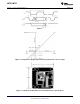
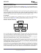
Simplified Block Diagram
Figure 1.
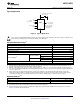
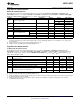
Connection Diagram
LM75B, LM75C, SOIC and VSSOP
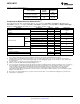
PIN DESCRIPTIONS
Label Pin # Function Typical Connection
I
2
C Serial Bi-Directional Data Line.
SDA 1 From Controller, tied to a pull-up resistor or current source
Open Drain.
SCL 2 I
2
C Clock Input From Controller, tied to a pull-up resistor or current source
Over temperature Shutdown.
O.S. 3 Pull–up Resistor, Controller Interrupt Line
Open Drain Output
GND 4 Power Supply Ground Ground
DC Voltage from 3V to 5.5V; 100 nF bypass capacitor with 10 µF
+V
S
8 Positive Supply Voltage Input
bulk capacitance in the near vicinity
A0–A2 7,6,5 User-Set I
2
C Address Inputs Ground (Low, “0”) or +V
S
(High, “1”)
2 Submit Documentation Feedback Copyright © 2009–2013, Texas Instruments Incorporated
Product Folder Links: LM75B LM75C