
Datasheet


LM75B, LM75C
www.ti.com
SNIS153B –JULY 2009–REVISED MARCH 2013
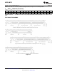
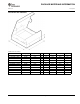
An inadvertent 8-bit read from a 16-bit register, with the D7 bit low, can cause the LM75 to stop in a state where
the SDA line is held low as shown in Figure 11. This can prevent any further bus communication until at least 9
additional clock cycles have occurred. Alternatively, the master can issue clock cycles until SDA goes high, at
which time issuing a “Stop” condition will reset the LM75.
Figure 11. Inadvertent 8-Bit Read from 16-Bit Register where D7 is Zero (“0”)
POINTER REGISTER (Selects which registers will be read from or written to):
P7 P6 P5 P4 P3 P2 P1 P0
0 0 0 0 0 Register Select
P0-P1: Register Select:
P2 P1 P0 Register
0 0 0 Temperature (Read only) (Power-up default)
0 0 1 Configuration (Read/Write)
0 1 0 T
HYST
(Read/Write)
0 1 1 T
OS
(Read/Write)
P3–P7: Must be kept zero.
TEMPERATURE REGISTER (Read Only):
D15 D14 D13 D12 D11 D10 D9 D8 D7 D6 D5 D4 D3 D2 D1 D0
MSB Bit 7 Bit 6 Bit 5 Bit 4 Bit 3 Bit 2 Bit 1 LSB X X X X X X X
D0–D6: Undefined. D7–D15: Temperature Data. One LSB = 0.5°C. Two's complement format.
CONFIGURATION REGISTER (Read/Write):
D7 D6 D5 D4 D3 D2 D1 D0
0 0 0 Fault Queue O.S. Polarity Cmp/Int Shutdown
Power up default is with all bits “0” (zero).
D0: Shutdown: When set to 1 the LM75 goes to low power shutdown mode.
D1: Comparator/Interrupt mode: 0 is Comparator mode, 1 is Interrupt mode.
D2: O.S. Polarity: 0 is active low, 1 is active high. O.S. is an open-drain output under all conditions.
D3–D4: Fault Queue: Number of faults necessary to detect before setting O.S. output to avoid false tripping due
to noise. Faults are determind at the end of a conversion. See specified temperature conversion time in the
Temperature-to-Digital Converter Characteristics table.
D4 D3 Number of Faults
0 0 1 (Power-up default)
0 1 2
1 0 4
1 1 6
Copyright © 2009–2013, Texas Instruments Incorporated Submit Documentation Feedback 11
Product Folder Links: LM75B LM75C