
Datasheet


LM6171
SNOS745C –MAY 1998–REVISED MARCH 2013
www.ti.com
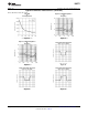
DRIVING CAPACITIVE LOADS
Amplifiers driving capacitive loads can oscillate or have ringing at the output. To eliminate oscillation or reduce
ringing, an isolation resistor can be placed as shown below in Figure 61. The combination of the isolation resistor
and the load capacitor forms a pole to increase stablility by adding more phase margin to the overall system. The
desired performance depends on the value of the isolation resistor; the bigger the isolation resistor, the more
damped the pulse response becomes. For LM6171, a 50Ω isolation resistor is recommended for initial
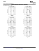
evaluation. Figure 62 shows the LM6171 driving a 200 pF load with the 50Ω isolation resistor.
Figure 61. Isolation Resistor Used to Drive Capacitive Load
Figure 62. The LM6171 Driving a 200 pF Load with a 50Ω Isolation Resistor
POWER DISSIPATION
The maximum power allowed to dissipate in a device is defined as:
P
D
= (T
J(max)
− T
A
)/θ
JA
where
• P
D
is the power dissipation in a device
• T
J(max)
is the maximum junction temperature
• T
A
is the ambient temperature
• θ
JA
is the thermal resistance of a particular package (2)
For example, for the LM6171 in a SOIC-8 package, the maximum power dissipation at 25°C ambient
temperature is 730 mW.
20 Submit Documentation Feedback Copyright © 1998–2013, Texas Instruments Incorporated
Product Folder Links: LM6171