
Datasheet
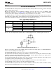
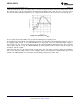


Table Of Contents
- FEATURES
- Applications
- DESCRIPTION
- Absolute Maximum Ratings
- Operating Ratings
- 5.0V DC Electrical Characteristics
- 5.0V AC Electrical Characteristics
- 2.7V DC Electrical Characteristics
- 2.7V AC Electrical Characteristics
- 24V DC Electrical Characteristics
- 24V AC Electrical Characteristics
- Typical Performance Characteristics
- Application Information
- Revision History
LM6152, LM6154
www.ti.com
SNOS752D –MAY 1999–REVISED MARCH 2013
APPLICATION INFORMATION
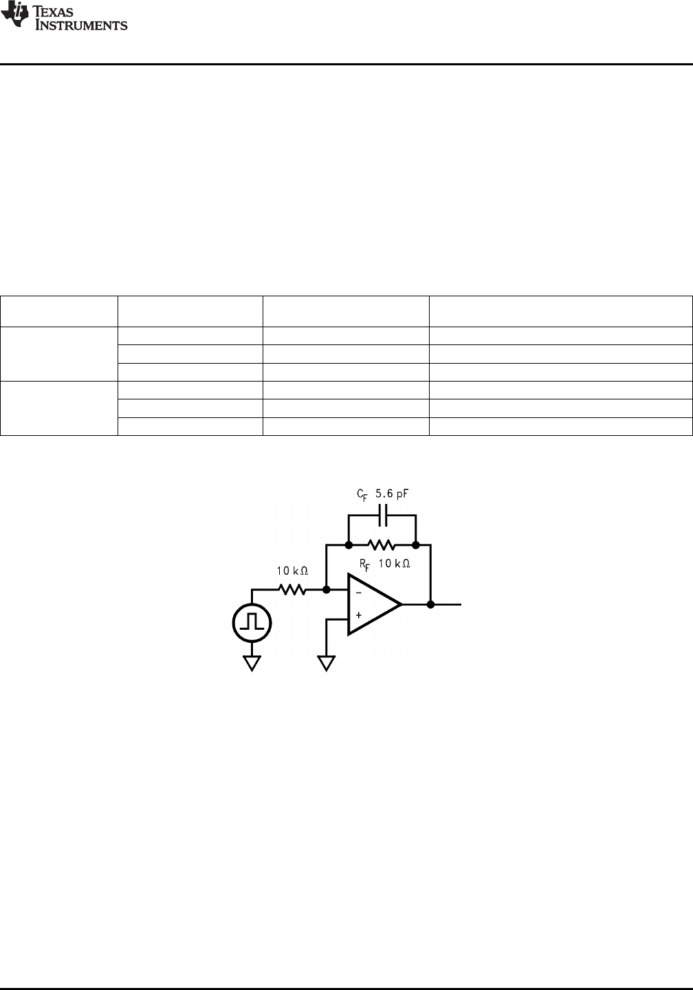
The LM6152/LM6154 is ideally suited for operation with about 10 kΩ (Feedback Resistor, R
F
) between the output
and the negative input terminal.
With R
F
set to this value, for most applications requiring a close loop gain of 10 or less, an additional small
compensation capacitor (C
F
) (see Figure 28) is recommended across R
F
in order to achieve a reasonable
overshoot (10%) at the output by compensating for stray capacitance across the inputs.
The optimum value for C
F
can best be established experimentally with a trimmer cap in place since its value is
dependant on the supply voltage, output driving load, and the operating gain. Below, some typical values used in
an inverting configuration and driving a 10 kΩ load have been tabulated for reference:
Table 1. Typical BW (−3 dB) at Various
Supply Voltage and Gains
V
S
C
F
BW (−3 dB)
Gain
Volts pF MHz
−1 5.6 4
3 −10 6.8 1.97
−100 None 0.797
−1 2.2 6.6
24 −10 4.7 2.2
−100 None 0.962
In the non-inverting configuration, the LM6152/LM6154 can be used for closed loop gains of +2 and above. In
this case, also, the compensation capacitor (C
F
) is recommended across R
F
(= 10 kΩ) for gains of 10 or less.
Figure 28. Typical Inverting Gain Circuit A
V
= −1
Because of the unique structure of this amplifier, when used at low closed loop gains, the realizable BW will be
much less than the GBW product would suggest.
The LM6152/LM6154 brings a new level of ease of use to op amp system design.
The greater than rail-to-rail input voltage range eliminates concern over exceeding the common-mode voltage
range. The rail-to-rail output swing provides the maximum possible dynamic range at the output. This is
particularly important when operating on low supply voltages.
The high gain-bandwidth with low supply current opens new battery powered applications where higher power
consumption previously reduced battery life to unacceptable levels.
The ability to drive large capacitive loads without oscillating functional removes this common problem.
To take advantage of these features, some ideas should be kept in mind.
The LM6152/LM6154, capacitive loads do not lead to oscillations, in all but the most extreme conditions, but they
will result in reduced bandwidth. They also cause increased settling time.
Copyright © 1999–2013, Texas Instruments Incorporated Submit Documentation Feedback 11
Product Folder Links: LM6152 LM6154