
Datasheet


LM555
www.ti.com
SNAS548B –MAY 2004–REVISED JULY 2006
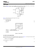
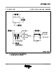
LINEAR RAMP
When the pullup resistor, R
A
, in the monostable circuit is replaced by a constant current source, a linear ramp is
generated. Figure 13 shows a circuit configuration that will perform this function.
Figure 13.
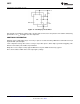
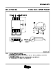
Figure 14 shows waveforms generated by the linear ramp.
The time interval is given by:
(6)
V
BE
≃ 0.6V (7)
V
CC
= 5V Top Trace: Input 3V/Div.
TIME = 20μs/DIV. Middle Trace: Output 5V/Div.
R
1
= 47kΩ Bottom Trace: Capacitor Voltage 1V/Div.
R
2
= 100kΩ
R
E
= 2.7 kΩ
C = 0.01 μF
Figure 14. Linear Ramp
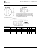
50% DUTY CYCLE OSCILLATOR
For a 50% duty cycle, the resistors R
A
and R
B
may be connected as in Figure 15. The time period for the output
high is the same as previous, t
1
= 0.693 R
A
C. For the output low it is t
2
=
(8)
Thus the frequency of oscillation is
(9)
Copyright © 2004–2006, Texas Instruments Incorporated Submit Documentation Feedback 11
Product Folder Links: LM555