
Datasheet


Table Of Contents
- AN-1878 LM5085 Evaluation Board
t
OFF(CL)
=
(V
FB
x 0.93) + 0.28V
4 x 10
-6
x
((V
IN
/31) + 0.15)
www.ti.com
Load Current Derating
5 Load Current Derating
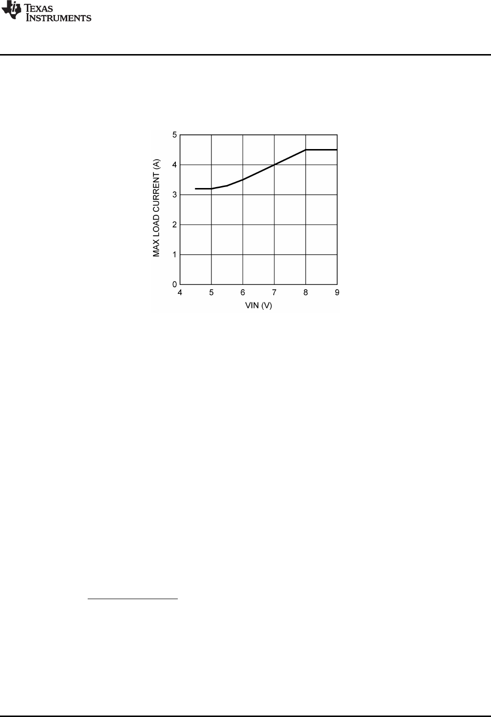
Although the maximum load current for this evaluation board is specified as 4.5A, the data sheet for the
Si7465 PFET specifies a maximum continuous current of 3.2A. Since the input current, which is the
average current though Q1, increases as the input voltage is decreased, the load current must be derated
at low input voltage, seeFigure 2.
Figure 2. Maximum Load Current Derating
6 Operating at Low Voltage
When the input voltage is less than 5 V the PFET (Q1) is on continuously (100% duty cycle), and the
output voltage is equal to the input voltage, minus voltage drops across the sense resistor, Q1 and the
inductor. As the input voltage is increased above 5 V, switching commences at the PGATE pin and the
SW node as the LM5085 regulates the output at 5 V. Since the LM5085 does not have a required
minimum off-time, the circuit transitions smoothly from 100% duty cycle to a regulated output.
7 Current Limit
The LM5085 peak current limit detection operates by sensing the voltage across either the R
DS(ON)
of Q1,
or a sense resistor (R5), during the on-time and comparing it to the voltage across R3 at the ADJ pin. The
current limit threshold is reached when the sensed voltage exceeds the voltage across R3. When current
limit is reached Q1 is immediately switched off. The current limit function is much more accurate and
stable over temperature when a sense resistor is used. The R
DS(ON)
of a MOSFET has a wide process
variation and a large temperature coefficient.
Current sensing is disabled for a blanking time of ≊100 ns at the beginning of each on-time to prevent
false triggering of the current limit comparator due to leading edge current spikes. After Q1 is turned off
due to current limit detection, Q1 is held off for a longer-than-normal off-time. The extended off-time is a
function of the input voltage and the voltage at the FB pin, as shown below in the graph “Current Limit Off-
time vs. V
IN
and V
FB
”. The current limit off-time can be calculated from Equation 2:
(2)
The longer-than-normal forced off-time allows the inductor current to decrease to a low level before the
next on-time. This cycle-by-cycle monitoring, followed by a long forced off-time, provides effective
protection from output load faults over a wide range of operating conditions.
3
SNVA357B–October 2008–Revised April 2013 AN-1878 LM5085 Evaluation Board
Submit Documentation Feedback
Copyright © 2008–2013, Texas Instruments Incorporated