
Datasheet


LM5025
UVLO
PGND
AGND
COMP
OUT_A
OUT_B
VCC
SS
RT
SYNC
REF
TIME
RAMP
CS1
VIN
V
IN
35V - 78V
V
OUT
3.3V
UP/DOWN
SYNC
ERROR
AMP and
ISOLATION
CS2
-+
www.ti.com
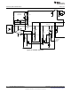
OUTSR Drive
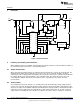
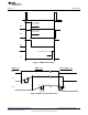
Figure 4. Typical Forward Converter
7 OUTSR Drive
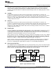
The LM5027 has a dedicated pin (OUTSR) to drive the synchronous rectifier free wheeling MOSFET
through a drive transformer as shown in Figure 5. When the converter starts-up, the OUTSR drive is held
low and the freewheeling MOSFET is turned-off. As a result, no output current will sink into the converter.
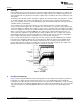
The OUTSR is enabled after the primary side soft-start reaches approximately 4.0V. The OUTSR delay
was added to ensure that the power supply output voltage is up and in regulation prior to the freewheeling
MOSFET being turned-on, refer to Figure 6 and Figure 7. The OUTSR drive is soft-started; a capacitor on
the SSSR pin is released and is charged with a 25 µA current source, slowly increasing the duty cycle of
the freewheeling FET’s duty cycle.
5
SNVA400B–August 2009–Revised May 2013 AN-1976 LM5027 Evaluation Board
Submit Documentation Feedback
Copyright © 2009–2013, Texas Instruments Incorporated