
Datasheet


Start-Up
www.ti.com
5 Start-Up
Power supplies have a soft-start circuit(s) to control their output voltage when input power is applied. The
soft-start sequence limits the peak inrush current as the output capacitors are charged, and prevents the
output voltage from over-shooting. In most power supplies there are primary side and secondary side soft-
start circuits.
The primary side soft-start circuit is generally in a primary side controller and the soft-start time is set with
an external capacitor. The function of the primary side soft-start circuit is to slowly increasing the duty
cycle of the controller from zero to the maximum duty cycle. The maximum duty cycle varies based on the
controller and the circuit topology.
The secondary side soft-start circuit connects a resistor/capacitor from the secondary side voltage
reference to the positive input of the error amplifier. The soft-start time is set by the resistor/capacitor time
constant and works by ramping up the voltage reference on the secondary side error amplifier. The output
of the error amplifier is fed across the isolation boundary to the primary side controller compensation input
which is connected to the controller PWM input. The voltage at the compensation input increases to a
value required for regulation as determined by the voltage feedback loop. The secondary side soft-start
along with the primary side soft-start work together to control the duty cycle on start-up to controlling the
power supplies output start-up time, and limit the stress on the power components.
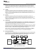
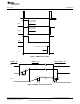
Figure 3 shows the primary and secondary side soft-start sequence using the LM5027 into an electronic
load. After Vin is applied the primary side soft-start ramps up. When the voltage on the LM5027 SS pin
reached 1.0 V the output drives start and power is delivered to the secondary of the transformer. The
power supply output rises and the secondary side soft-start circuit begins to ramp-up. The output of the
DC-DC converter monotonically increased with no overshoot to 3.3 V out.
Figure 3. Soft-Start
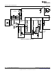
6 Pre-Bias Load Start-Up
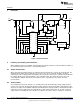
Figure 4 shows a typical Forward Converter topology with an active clamp using self-driven synchronous
rectification. It’s simple and very efficient; however there are some disadvantages when starting this
topology into a pre-biased load. The first occurs because the synchronous rectification is on the secondary
side of the transformer and without adding intelligence the output current will flow into the converter via the
output choke and the free wheeling MOSFET when the converter starts-up or shut down with pre-bias
voltage.
4
AN-1976 LM5027 Evaluation Board SNVA400B–August 2009–Revised May 2013
Submit Documentation Feedback
Copyright © 2009–2013, Texas Instruments Incorporated