
Datasheet


CS
VIN
UVLO
OTP
RAMP
TIME3
REF
RT
TIME1
TIME2
SS
RES
SSSR
COMP
OUTA
OUTB
OUTSR
AGND
PGND
VCC
ERROR AMP and
ISOLATION
VOUT
VIN
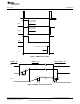
LM5027
Schematic
www.ti.com
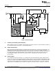
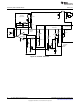
3 Schematic
Figure 1. Board Schematic
4 Powering and Loading Considerations
When applying power to the LM5027 evaluation board certain precautions need to be followed. A failure or
mis-connection can present itself in a very alarming manner.
4.1 Proper Connections
When operated at low input voltages the evaluation board can draw up to 3.5A of current at full load. The
maximum rated output current is 30A. Be sure to choose the correct connector and wire size when
attaching the source supply and the load. Monitor the current into and out of the evaluation board. Monitor
the voltage directly at the output terminals of the evaluation board. The voltage drop across the load
connecting wires will give inaccurate measurements; this is especially true for accurate efficiency
measurements.
4.2 Source Power
The evaluation board can be viewed as a constant power load. At low input line voltage (36V) the input
current can reach 3.5A, while at high input line voltage (78V) the input current will be approximately 1.5A.
Therefore too fully test the LM5027 evaluation board a DC power supply capable of at least 80V and 4A is
required. The power supply must have adjustments for both voltage and current. An accurate readout of
output current is desirable since the current is not subject to loss in the cables as voltage is. The power
2
AN-1976 LM5027 Evaluation Board SNVA400B–August 2009–Revised May 2013
Submit Documentation Feedback
Copyright © 2009–2013, Texas Instruments Incorporated