
Datasheet


80 Volt , 5 Amp
Power Supply
with
Current Meter
Current
probe
-
-
+
IN
Vout
LM5027
Evaluation Board
+
+
S+
S-
VoutRTN
1W
OSC
scope
220uF
Vout - 0.6 V
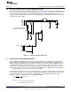
Pre-Bias Load Test Set-Up
www.ti.com
12 Pre-Bias Load Test Set-Up
For the Pre-bias start-up test, the circuit in Figure 15 was used. An external bias supply, through a 1.0
ohm resistor, was connected across the output terminals of the Evaluation Board.
13 Pre-Bias Load Start-Up Requirements
The Evaluation board Pre-Bias start-up requirements are:
During converter start-up the output shall rise monotonically and not sink current (into the converter) of
more than 50 mA.
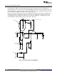
Figure 15. Isolated Synchronous MOSFET Drive Using a Transformer
14 Evaluation Board Results
Figure 16 shows the output of the Evaluation Board starting with a pre-bias voltage of 2.7 V. Under these
conditions the output voltage starts at 2.7 V and then increases monotonically to 3.3 V. The current into
the Evaluation board (sinking) is less than 50 mA. When the output voltage rise above the pre-bias voltage
there is approximately 400 mA of current out of (sourced) the Evaluation Board to charge the external 220
µF capacitor. After the external capacitor is charge to 3.3 V the current out of the power supply drop to
approximately 50 mA.
Figure 16. Pre-Bias StartUp
14
AN-1976 LM5027 Evaluation Board SNVA400B–August 2009–Revised May 2013
Submit Documentation Feedback
Copyright © 2009–2013, Texas Instruments Incorporated