
Datasheet


OUTSR
Gate of the Sync MOSFET is
Drven by a winging on T1 and is
isolated
T1
www.ti.com
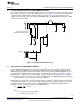
Synchronous Forward MOSFET Enabled
Figure 13. Pre-Bias Load Waveforms
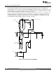
An alternative to using the circuit in Figure 12 is shown in Figure 14; an additional winding can be added
to the power transformer which can be used to drive the Forward Synchronous Rectifier MOSFET (M1).
This is a simple solution and should not add a lot of complexity to the transformer design.
Figure 14. Isolated Synchronous MOSFET Drive Using a Transformer
13
SNVA400B–August 2009–Revised May 2013 AN-1976 LM5027 Evaluation Board
Submit Documentation Feedback
Copyright © 2009–2013, Texas Instruments Incorporated