
Datasheet
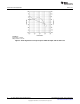


www.ti.com
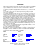
Performance Characteristics
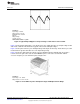
Conditions:
Input Voltage = 20VDC
Output Current = 150 mA
Bandwidth Limit = 20 MHz
Trace 1:
Output Voltage
Volts/div = 20 mV
Horizontal Resolution = 1 µs/div
Figure 4. Typical Output Ripple for an Input Voltage of 20V and a Load of 150 mA
Figure 4 shows typical output ripple, seen directly across the output capacitor, for an input voltage of 20V
and a load of 150 mA. This waveform is typical of most loads and input voltages.
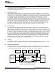
Figure 5 shows power efficiency over full input voltage and output current range. Peak efficiency is at full
rated load and is greater then 90% across the input voltage range.
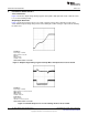
Figure 6 shows the small signal closed loop response with 20V input and 150 mA load current into a
resistive load. The gain curve starts at around 60dB the phase curve starts at around 45°. 0dB of
crossover frequency is at 11 kHz with a phase margin of 70°.
Conditions:
Input Voltage = 16 - 36VDC
Output Current = 10 mA - 150 mA
Figure 5. Power Efficiency Over Full Input Voltage and Output Current Range
5
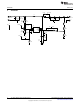
SNVA393B–March 2009–Revised April 2013 AN-1956 LM5001 Boost Evaluation Board
Submit Documentation Feedback
Copyright © 2009–2013, Texas Instruments Incorporated