
Datasheet
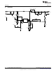
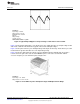

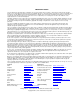

Scope Volt-meter Volt-meter Current-meter
36 Volt, 1 Amp
Power Supply
with Current
Meter
10 Watt, 1 Amp
Electronic Load
-
+
+
-
Evaluation Board
ON/OFF
(SHUTDOWN)
IN
OUT
Jumper
-
+
-
+
www.ti.com
Powering and Loading Considerations
3 Powering and Loading Considerations
When applying power to the LM5001 Boost evaluation board certain precautions need to be followed. A
misconnection can damage the board.
3.1 Proper Connections
When operated at low input voltages the evaluation board can draw up to 500mA of current at full load.
The maximum rated output current is 150mA. Be sure to choose the correct connector and wire size when
attaching the source supply and the load. Monitor the current into and out of the evaluation board. Monitor
the voltage directly at the output terminals of the evaluation board. The voltage drop across the load
connecting wires will give inaccurate measurements. This is especially true for accurate efficiency
measurements. When measuring output ripple with an oscilloscope. Do not use the wire ground lead for
the ground connection. The loop formed by the wire lead will pick up noise from the switching circuits and
make the ripple voltage look larger then it actually is. Instead use a spring ground clip on the exposed
ground ring on the scope probe to minimize the loop area of the ground lead. An alternative is to remove
the shroud covering the scope probe. Then touch the exposed scope probe ground connection to the
output ground terminal while simultaneously connecting the probe tip to the output terminal.
3.2 Source Power
The power supply and cabling must look like a low impedance voltage source to the evaluation board.
High inductance power supply leads like the type typically used for bench power supplies, could cause the
LM5001 to become unstable or have poor response to load transients. This is due to the inductance of the
power supply wiring interacting with the evaluation board input capacitor and causing a series resonant LC
oscillation at a frequency defined by the inductance of the input wiring and the value of the input capacitor.
In some cases it may be necessary to add an additional capacitor in parallel with input capacitor to move
the resonate frequency away from the unity gain crossover frequency of the LM5001. Twisting the input
supply lines together will reduce the inductance and potential for problems. Powering up at max rated
voltage or close to this voltage can cause damage due to the inductance of the supply lines. Over shoot
and ringing can be several volts under a sudden application of power. When operating near maximum
input voltage slowly ramp up the voltage to avoid overshoot.
3.3 Loading
An appropriate electronic load, with specified operation up to 48V maximum or more, is desirable. Monitor
both current and voltage at all times. Ensure there is sufficient cooling provided for the load.
3.4 Over Current Protection
The LM5001 monitors the peak current through the inductor on a cycle by cycle basis. If the inductor is
sized large enough to not saturate when operating at peak current limit. Then the short circuit can be left
on indefinitely with out damaging the device or causing it to go into thermal shutdown.
Figure 1. Typical Evaluation Setup
3
SNVA393B–March 2009–Revised April 2013 AN-1956 LM5001 Boost Evaluation Board
Submit Documentation Feedback
Copyright © 2009–2013, Texas Instruments Incorporated