
Datasheet

LM431
www.ti.com
SNVS020G –MAY 2000–REVISED APRIL 2013
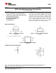
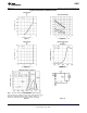
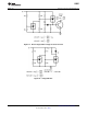
Typical Performance Characteristics
Input Current
vs
V
Z
Thermal Information
Figure 7. Figure 8.
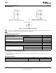
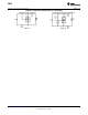
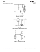
Input Current Dynamic Impedance
vs vs
V
Z
Frequency
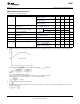
Figure 9. Figure 10.
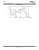
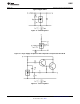
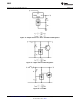
Stability Boundary Conditions
Note: The areas under the curves represent conditions that may
cause the device to oscillate. For curves B, C, and D, R2 and V
+
were
adjusted to establish the initial V
Z
and I
Z
conditions with C
L
= 0. V
+
and C
L
were then adjusted to determine the ranges of stability.
Figure 11. Figure 12.
Copyright © 2000–2013, Texas Instruments Incorporated Submit Documentation Feedback 5
Product Folder Links: LM431