
Datasheet

LM431
SNVS020G –MAY 2000–REVISED APRIL 2013
www.ti.com
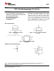
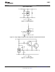
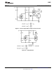
DC Test Circuits
Note: V
Z
= V
REF
(1 + R1/R2) + I
REF
• R1
Figure 4. Test Circuit for V
Z
= V
REF
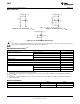
Figure 5. Test Circuit for V
Z
> V
REF
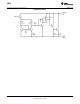
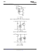
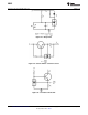
Figure 6. Test Circuit for Off-State Current
These devices have limited built-in ESD protection. The leads should be shorted together or the device placed in conductive foam
during storage or handling to prevent electrostatic damage to the MOS gates.
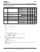
Absolute Maximum Ratings
(1)(2)
Storage Temperature Range −65°C to +150°C
Operating Temperature Range Industrial (LM431xI) −40°C to +85°C
Commercial (LM431xC) 0°C to +70°C
Soldering Information Infrared or Convection (20 sec.) 235°C
Wave Soldering (10 sec.) 260°C (lead temp.)
Cathode Voltage 37V
Continuous Cathode Current −10 mA to +150 mA
Reference Voltage −0.5V
Reference Input Current 10 mA
Internal Power Dissipation
(3)(4)
TO-92 Package 0.78W
SOIC Package 0.81W
SOT-23 Package 0.28W
(1) Absolute Maximum Ratings indicate limits beyond which damage to the device may occur. Electrical specifications do not apply when
operating the device beyond its rated operating conditions.
(2) If Military/Aerospace specified devices are required, please contact the TI Sales Office/ Distributors for availability and specifications.
(3) T
J Max
= 150°C.
(4) Ratings apply to ambient temperature at 25°C. Above this temperature, derate the TO-92 at 6.2 mW/°C, the SOIC at 6.5 mW/°C, the
SOT-23 at 2.2 mW/°C.
Operating Conditions
Min Max
Cathode Voltage V
REF
37V
Cathode Current 1.0 mA 100 mA
2 Submit Documentation Feedback Copyright © 2000–2013, Texas Instruments Incorporated
Product Folder Links: LM431